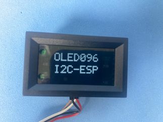
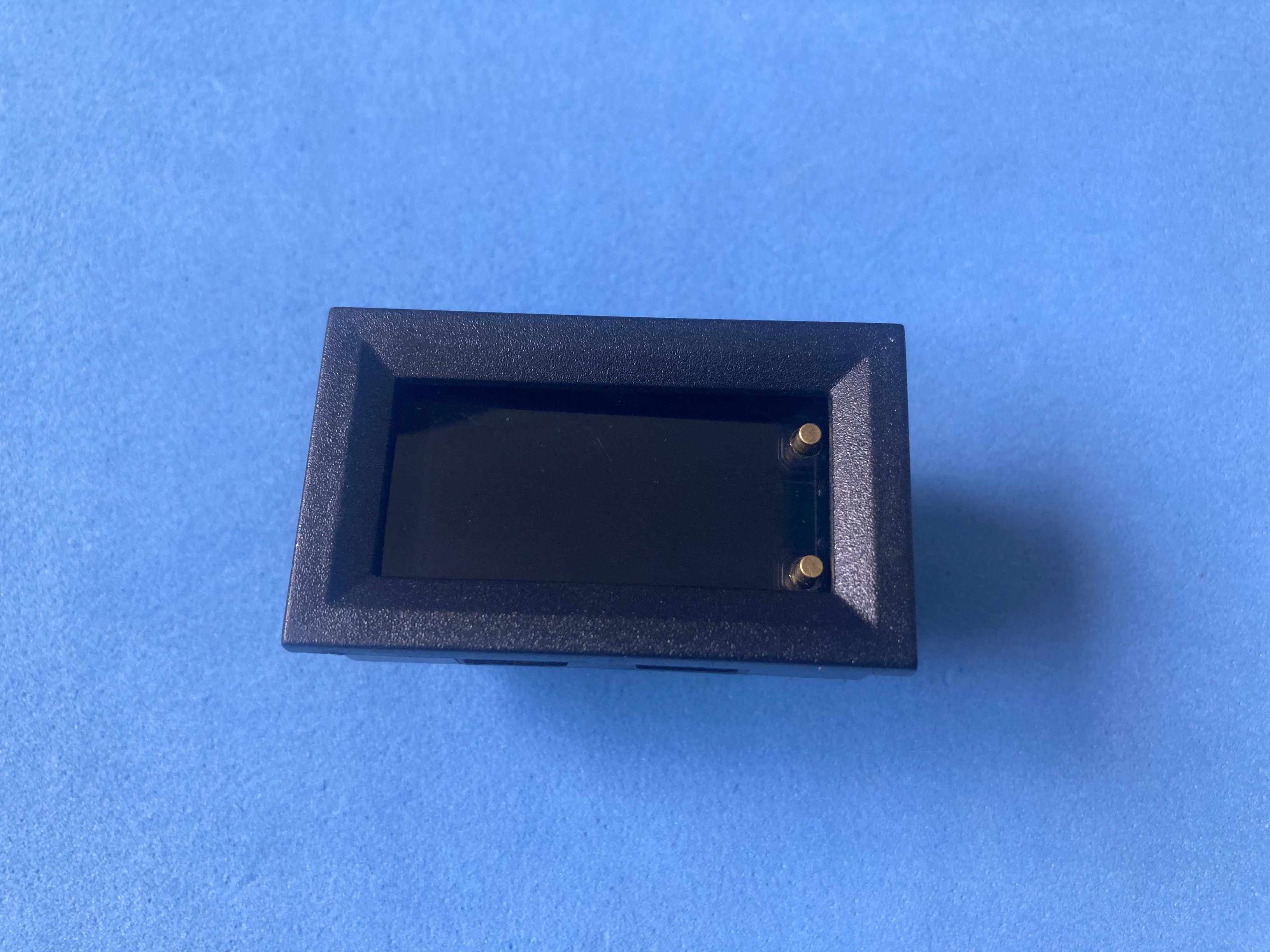
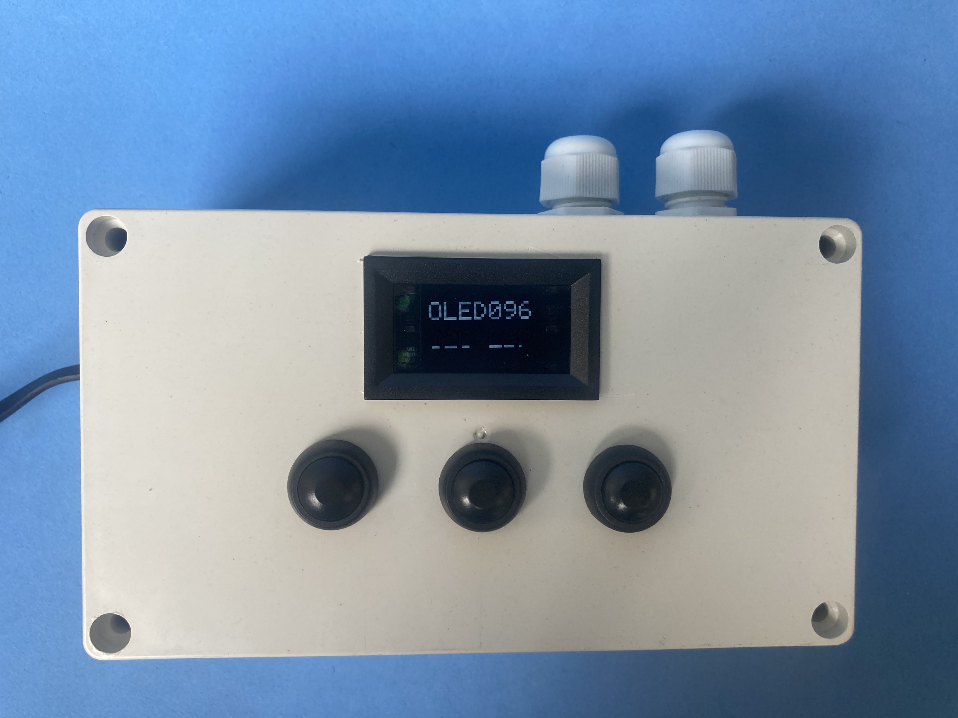
Panel-mount 0.96” bare OLED with screw terminals
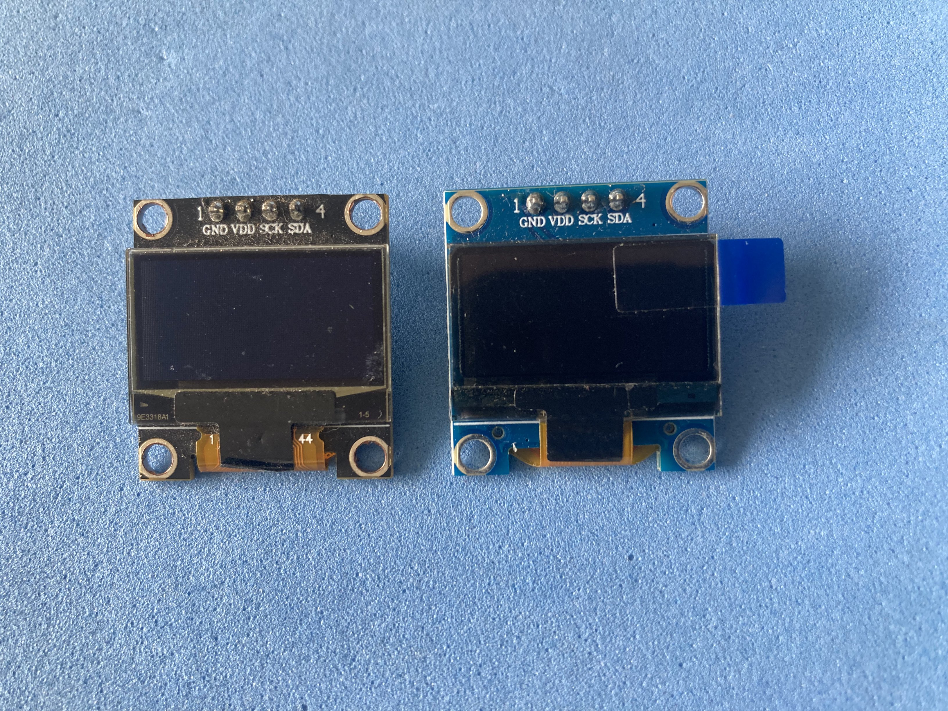
Small OLED modules look interchangeable at first glance, but mounting holes and the panel cutout needed for the display to show through rarely match between vendors. A clean panel installation usually means a precise display window plus four accurately placed screw holes. Those dimensions change from one module to the next.
This project packages a raw 0.96” I2C OLED with no intermediate processing module inside a 48×29 mm panel-mount enclosure with screw terminals. Build it only once across prototypes without resoldering or crimping custom cables.
Why?
Panel instruments in the 48×29 mm form factor share a practical semi-standard: one rectangular cutout, internal clips and a front bezel that hides imperfect edges. That idea was borrowed from low-cost DC panel meters, including the popular “9-in-1” voltage/current/power modules, which already use a two-board internal layout.
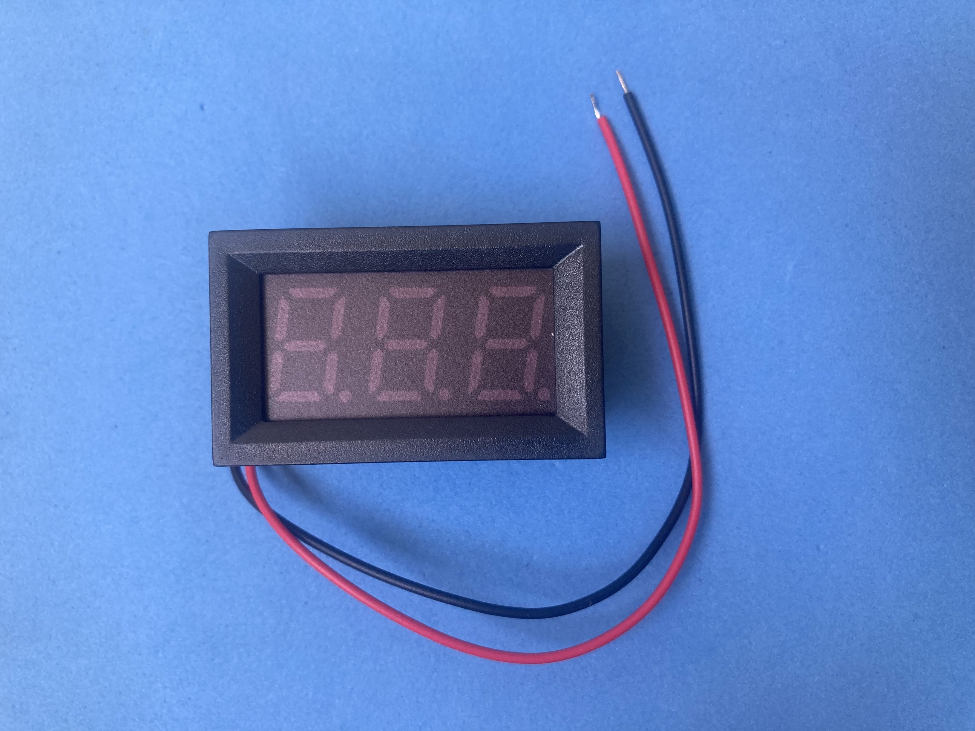
After searching for an off-the-shelf product that combined panel mounting, a dumb I2C display and robust screw terminals, nothing turned up at hobby quantities. The reference starting point was the popular “9-in-1” DC voltage/current/power panel meter in a 48×29 mm enclosure.
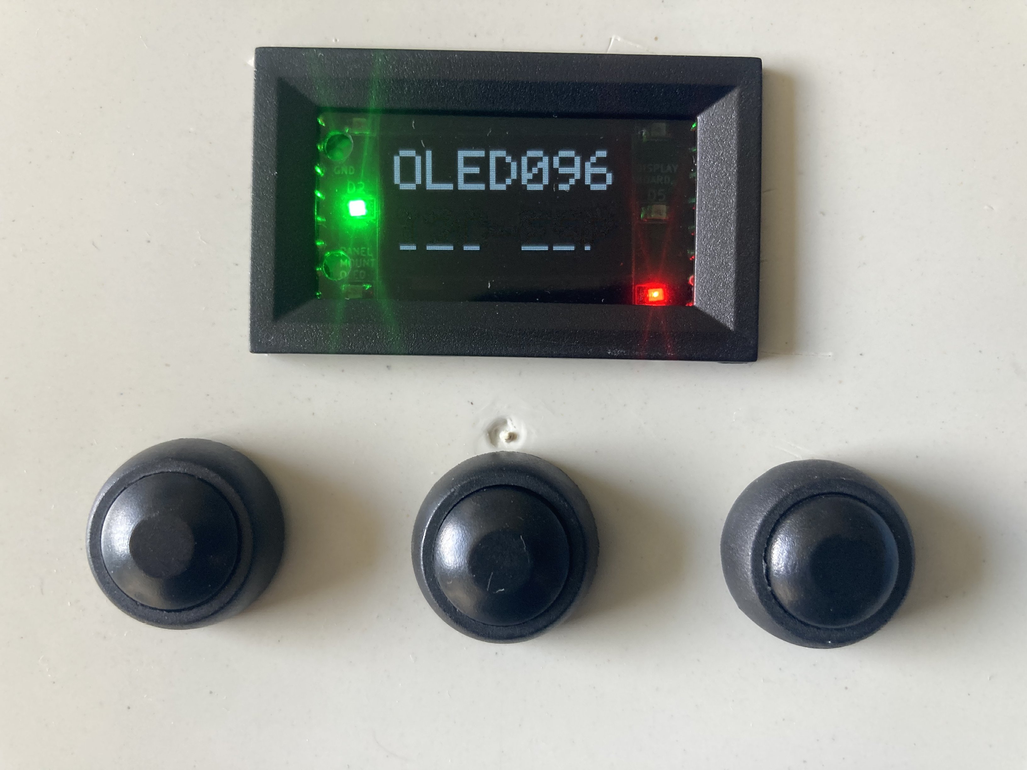
Core component: 0.96” OLED 128x64 bare screen I2C.

Key features:
- Open source hardware: KiCad sources and Gerbers on GitHub
- Raw I2C OLED interface (no on-board MCU)
- 48×29 mm panel-mount bezel tolerates a rough cutout
- Six independent 0805 indicator LEDs with separate anode/cathode terminals
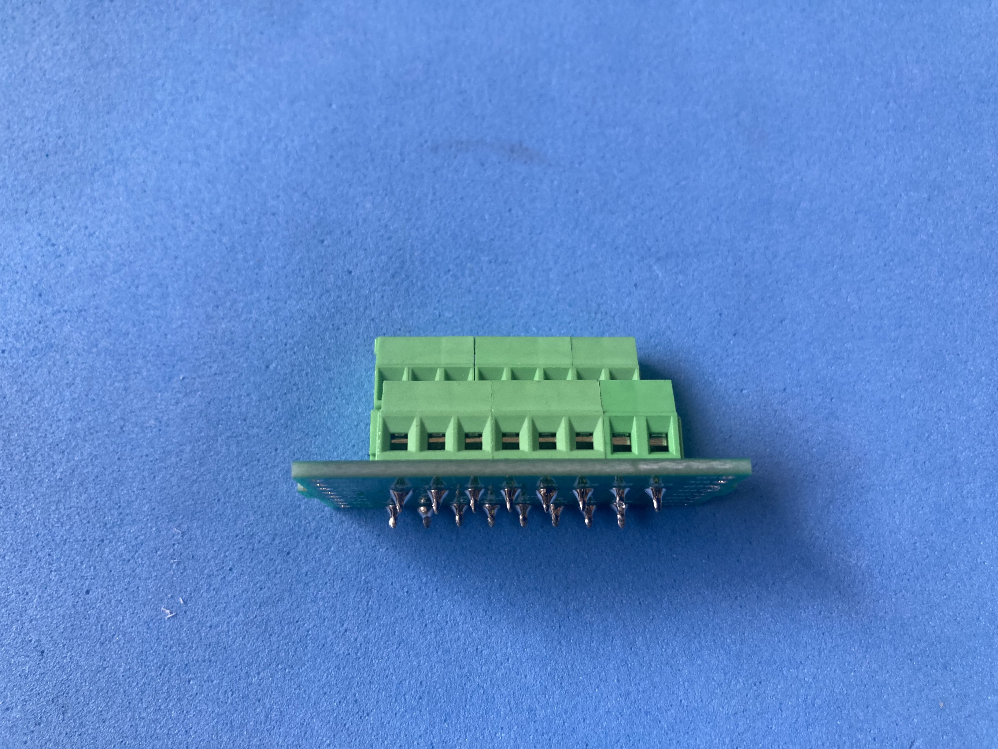
- Double-level 3.5 mm screw terminals for solid wire, stranded wire or Dupont leads
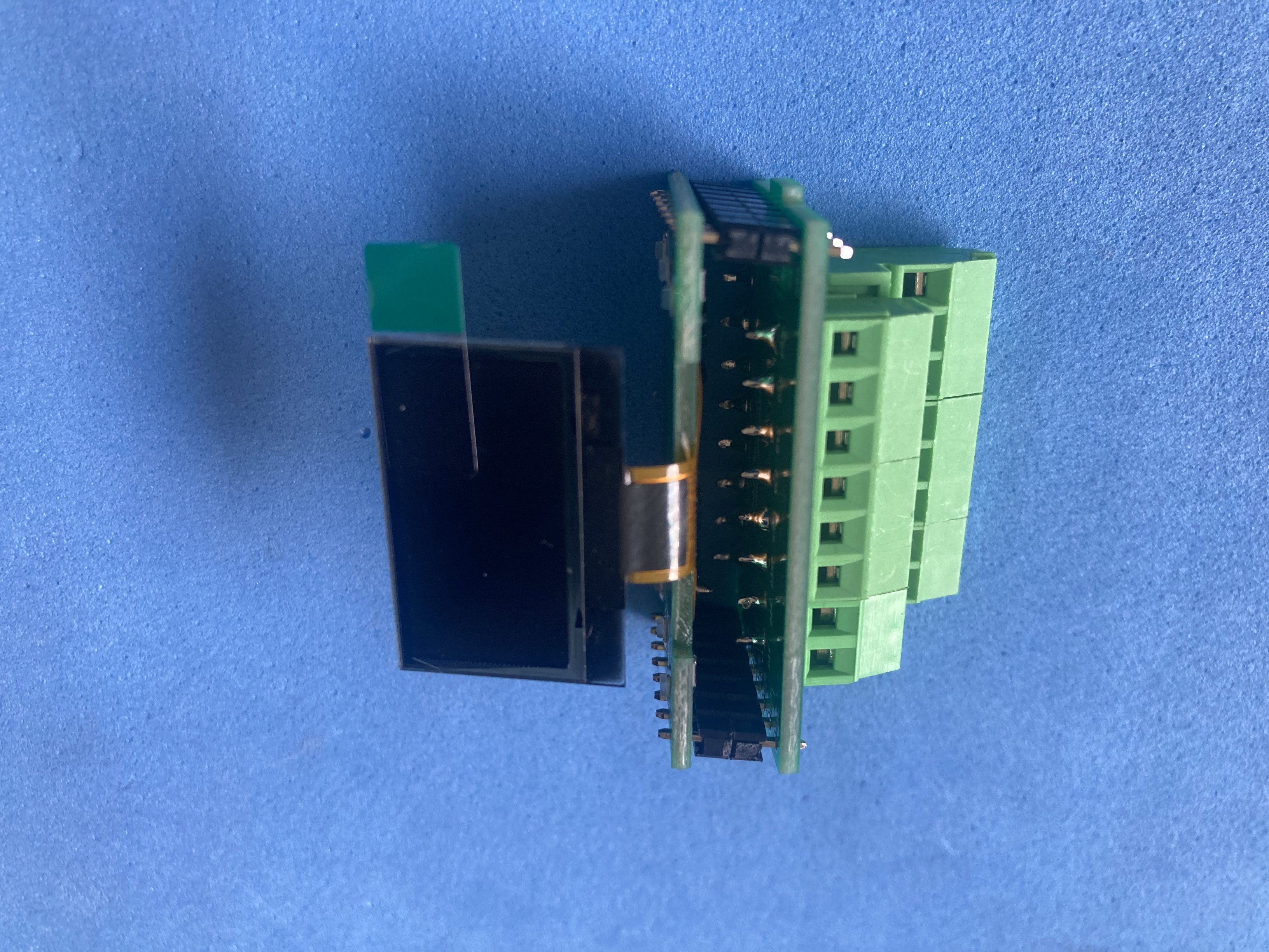
- Two-board stack: solder once, rewire many times across projects
Bill Of Materials
| Component | Buy link | Datasheet |
|---|---|---|
| SMD capacitor kit (0805) | Buy link | smd-capacitors.pdf |
| SMD LED (0805) | Buy link | smd-led-0805.pdf |
| SMD diode 1N4148 | Buy link | smd-diode-1n4148-melf.pdf |
| SMD resistor kit (0805) | Buy link | smd-resistors.pdf |
| Pin header 1x8 2.54 mm (male) | Buy link | single-row-male-header-2-54-pitch.pdf |
| PCB screw terminal double level 3.5 mm (2x8) | Buy link | pcb-screw-terminal-double-level-3-5.pdf |
| 0.96″ OLED 128x64 bare screen I2C | Buy link | oled-0-96-i2c-128x64-bare-screen.pdf |
| XC6206 3.3 V LDO regulator (SOT-23) | Buy link | xc6206.pdf |
Printed Circuit Boards
| PCB | Source files |
|---|---|
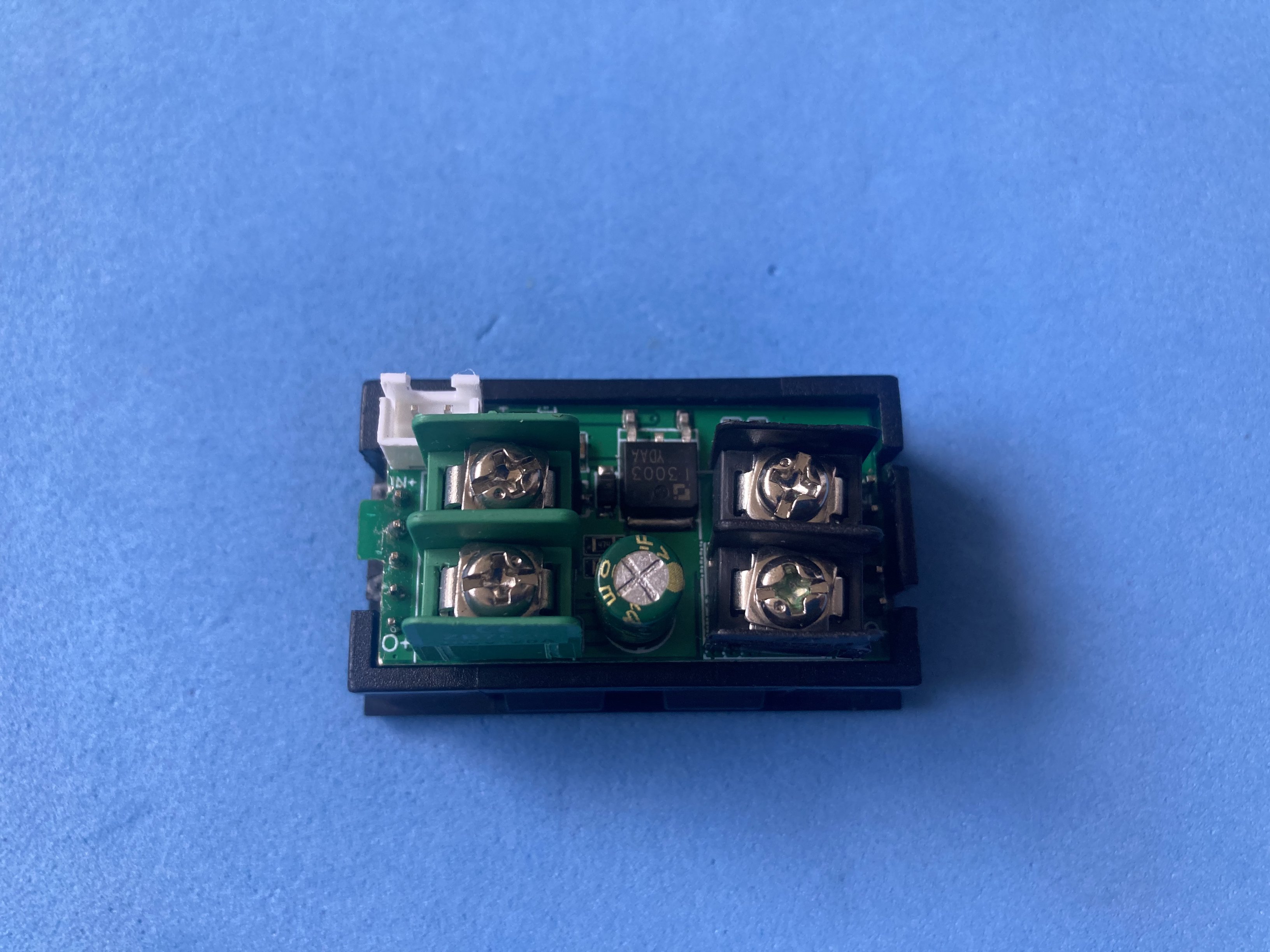
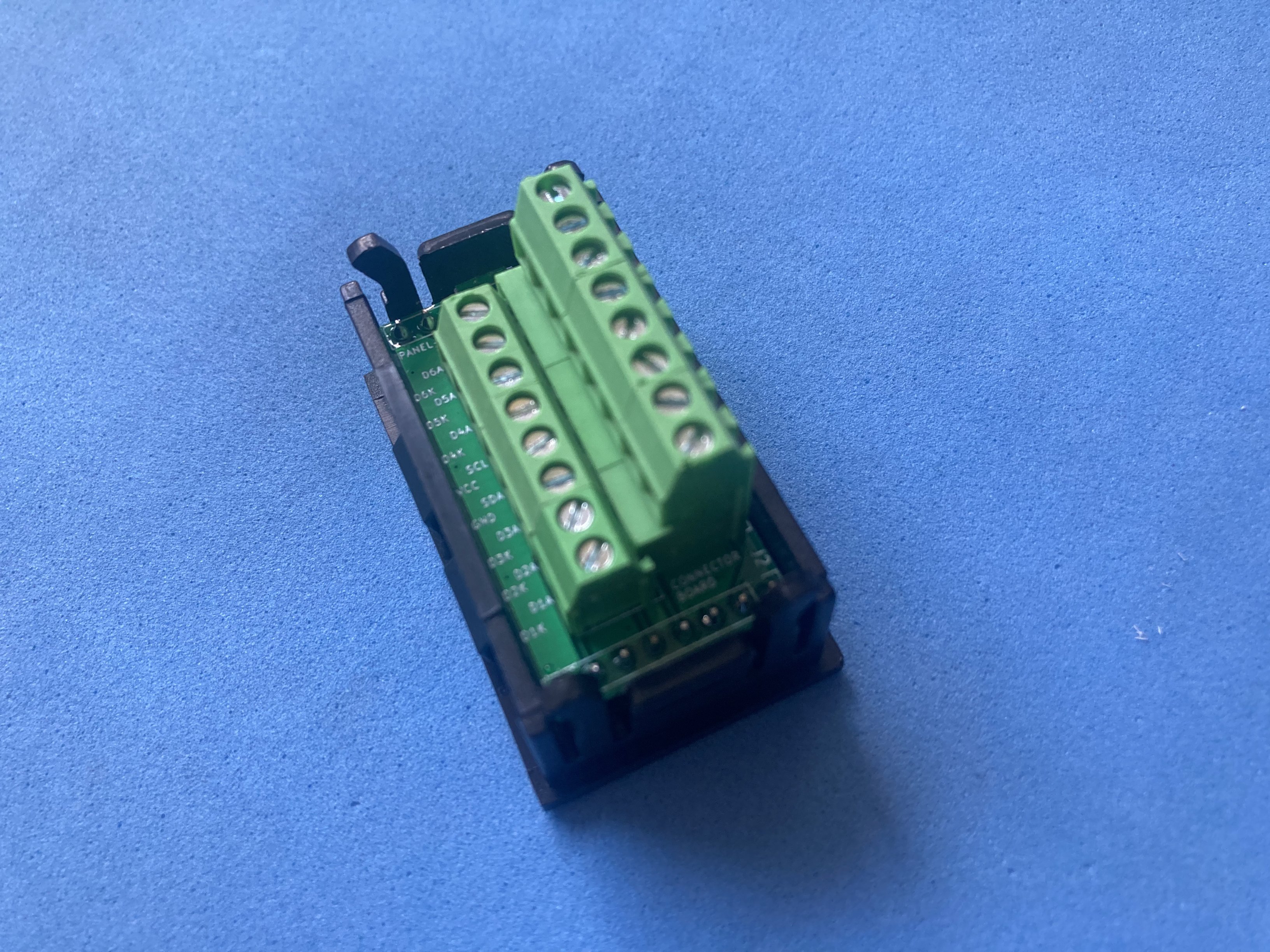
| Display board (OLED, regulator, LEDs) | panel-mount-oled-display/display-board |
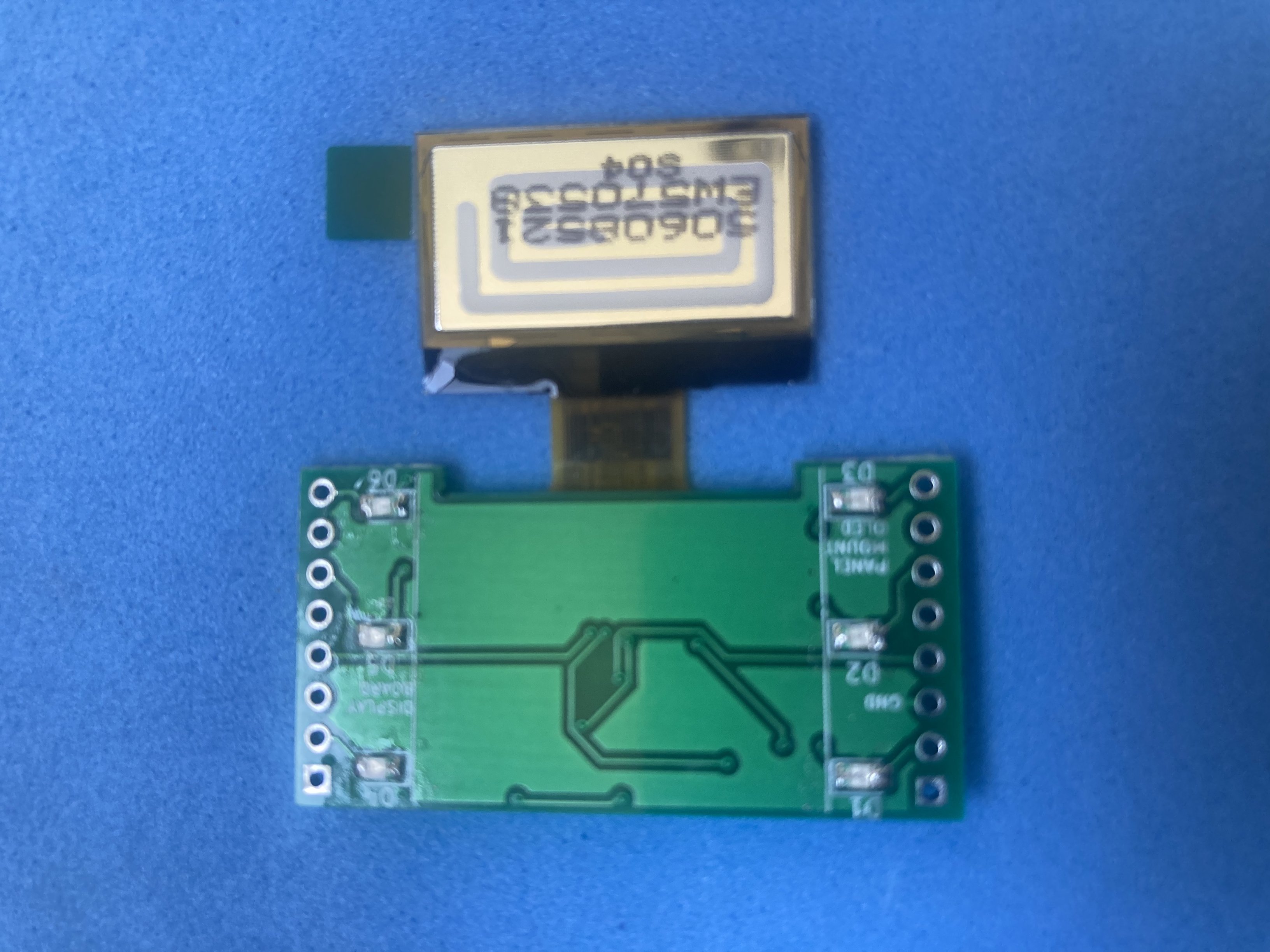
| Connector board (screw terminals) | panel-mount-oled-display/connector-board |
Electronic design
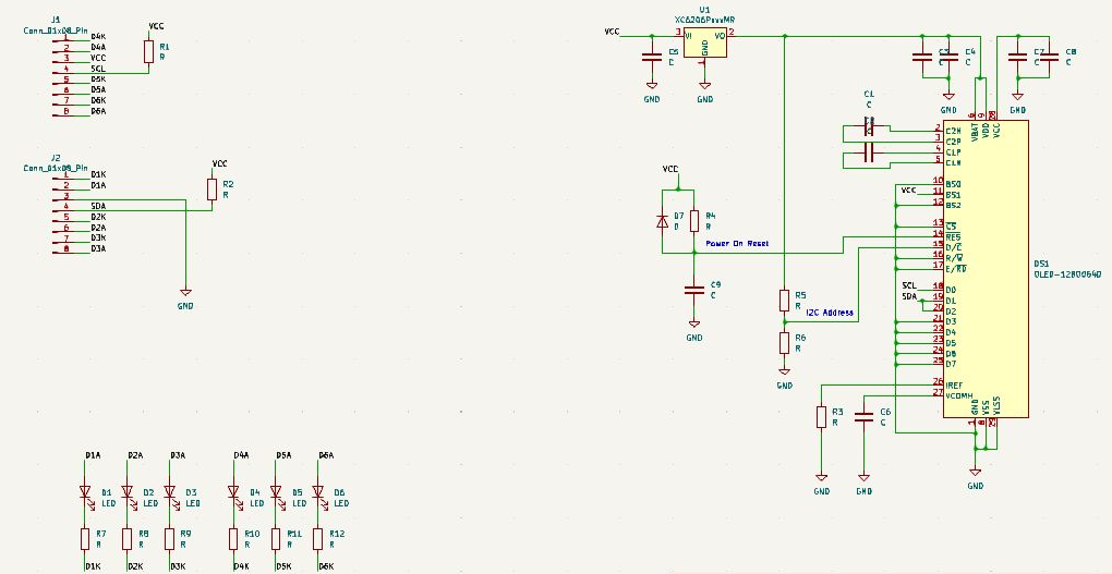
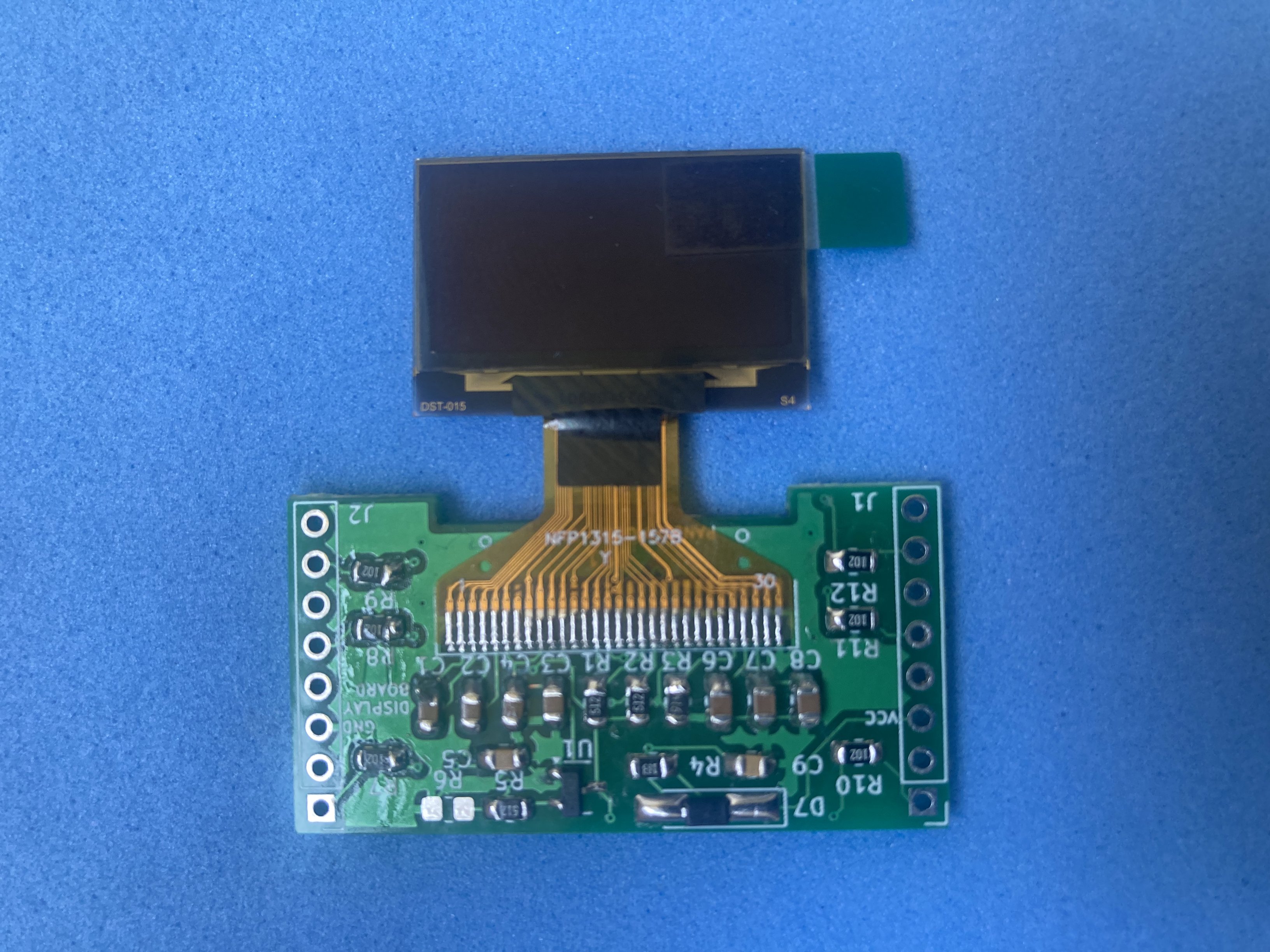
The design splits functionality across two boards joined by a 1×8 header. The display board carries the XC6206 3.3 V regulator, the OLED auto-reset network, I2C coupling, some capacitors used by the display’s internal DC/DC converter and six indicator LEDs with independent terminals. The connector board only routes to the double-level screw terminals. Full schematics and design notes are in the GitHub repository.
Assembly
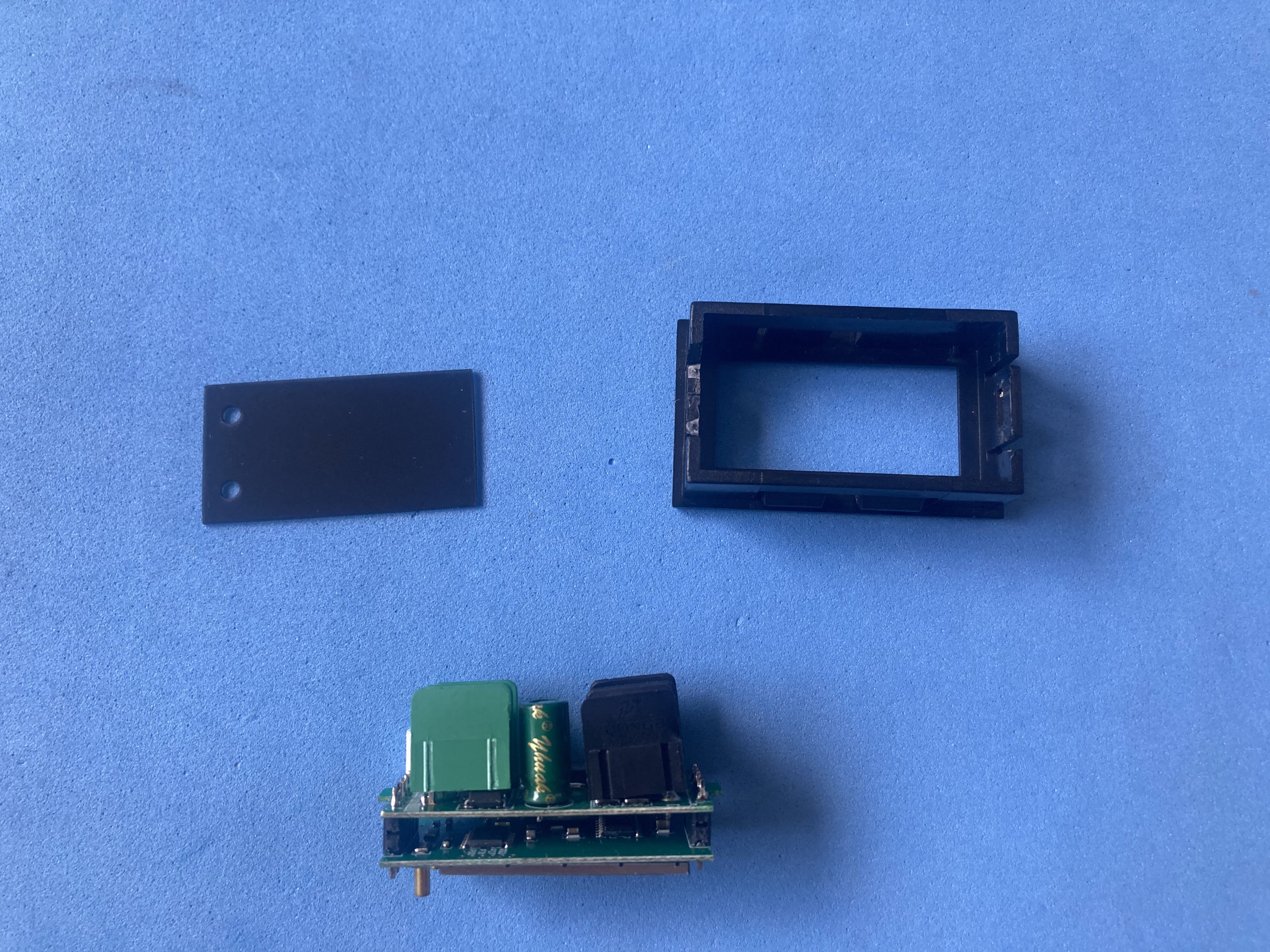
Manual build follows the two-board layout seen in cheap “9-in-1” panel meters. Solder the SMD parts on both PCBs first. The display board gets the flex OLED (0.7 mm pitch, 30 pins), the XC6206, the auto-reset network and six indicator LEDs. The connector board gets the double-level screw terminals. The flex display needs a T-tip iron; everything else is routine SMD work.
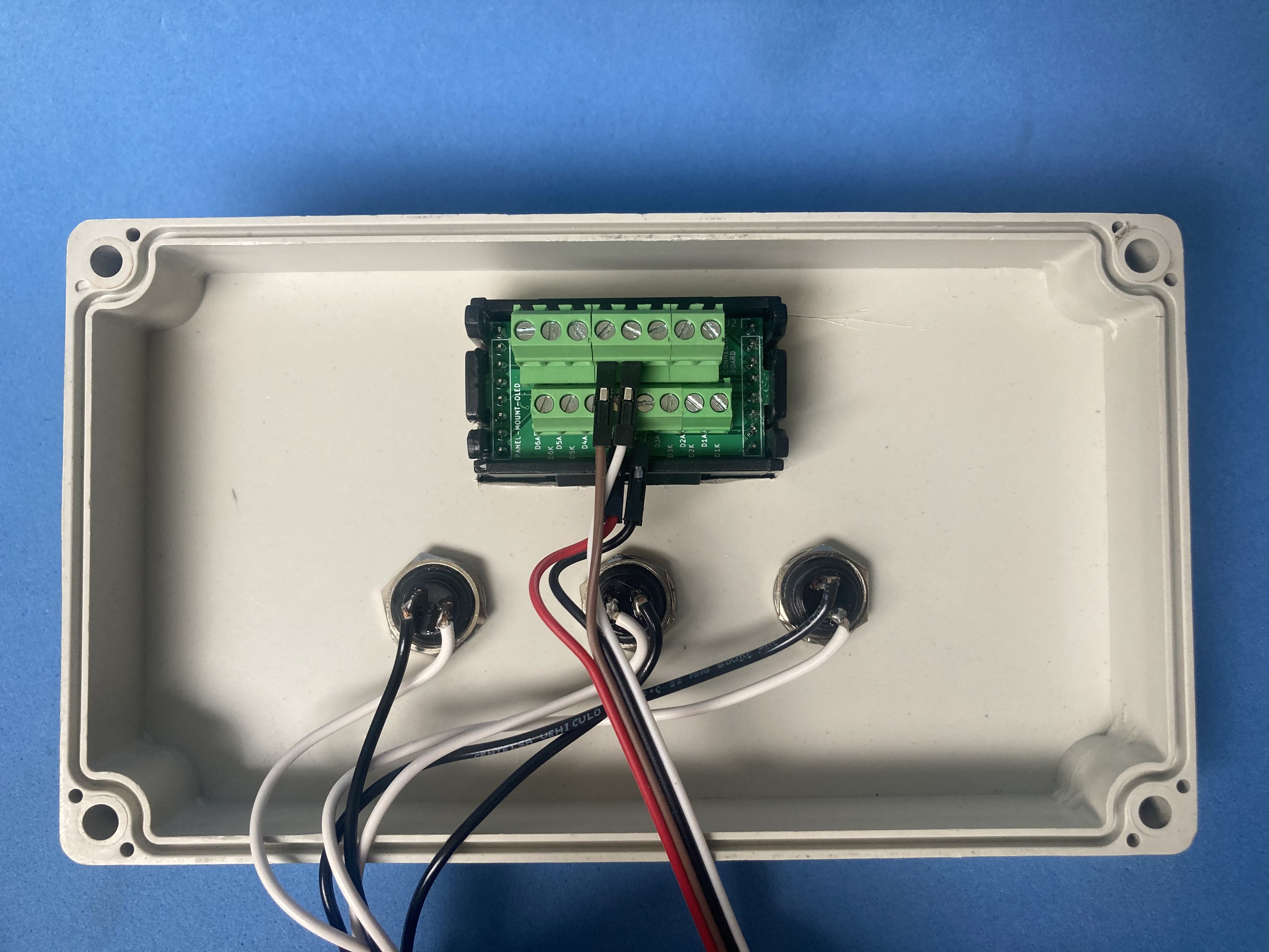
Stack the boards with 1×8 pin headers and a spacer between them so the terminals stay reachable from the side.
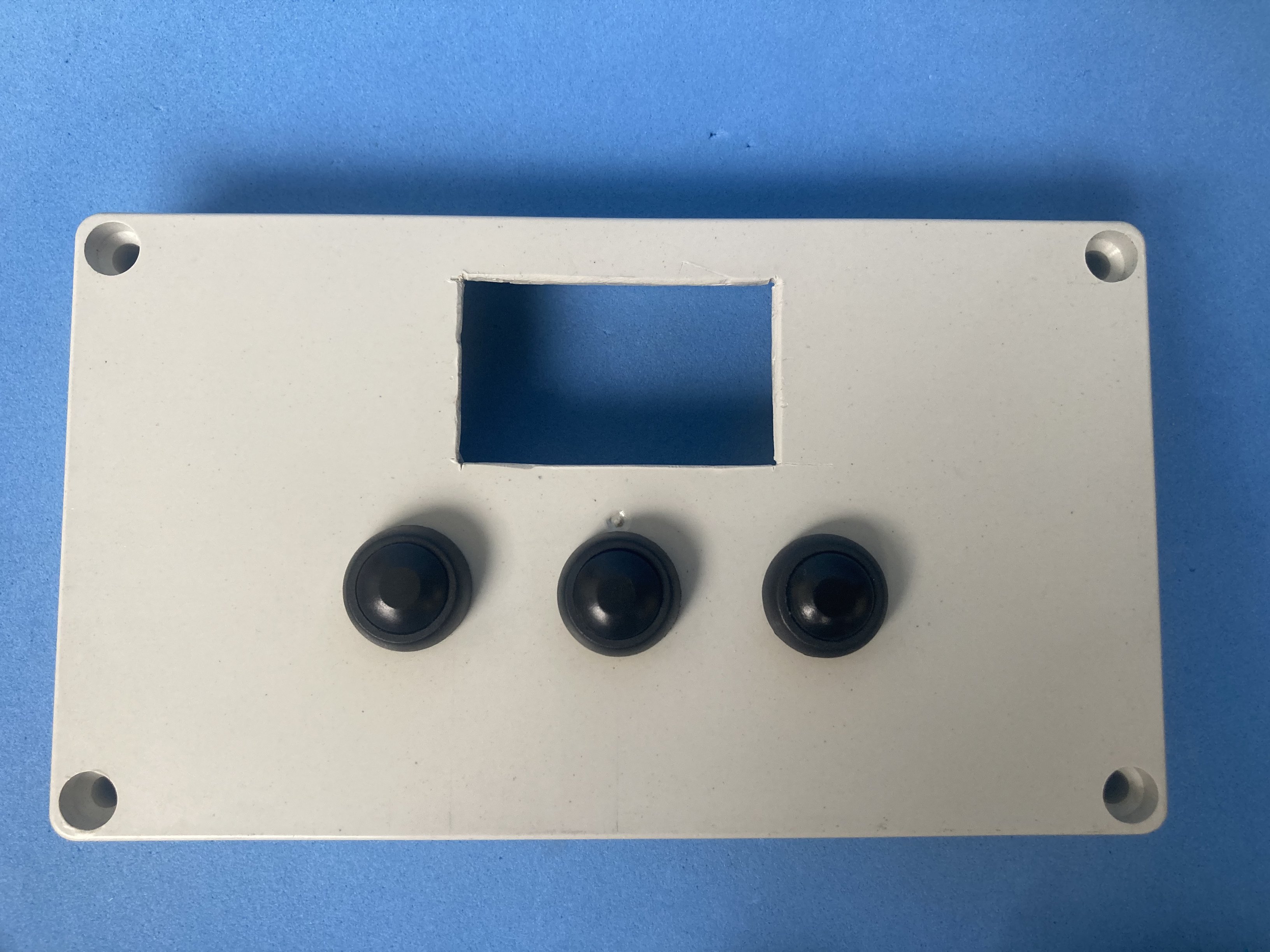
The case comes from a donor 48×29 mm panel meter (whichever is cheapest): strip the original electronics and reuse the front bezel and acrylic window, or cut a new dark translucent lens up to 1 mm thick. Slide the board stack into the case; internal clips hold the module without extra panel screws.
Software
This module has no firmware of its own. Any host with I2C (Arduino, RPi Pico, ESP32, etc.) can drive the SSD1306-compatible display and the six LED outputs through the screw terminals.
Customization
The design can be adapted around power input and how the indicator LEDs are used. A resistor can also be moved between two solder positions to choose between two possible I2C bus orientations.
Power source
The on-board XC6206 provides 3.3 V for the OLED from the VCC/GND screw terminals. Feed within the regulator and display ratings (typically 3.3-5 V at the input, depending on the exact XC6206 variant populated).
Expansion
Six 0805 LEDs are broken out with independent anode and cathode terminals, so each indicator can belong to a different circuit or ground domain. The bottom terminal row is tighter for Dupont plugs but holds firmly once inserted.
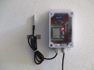
Sample application
Mount the module in a panel or bench enclosure and wire I2C (SCL, SDA, VCC, GND) from the microcontroller to the screw terminals. Route one or more of the six LED pairs to status signals (power OK, alarm, mode, etc.) on independent returns if needed. When the project ends, unscrew the leads and move the same assembly to the next prototype.
Optional components:
| Component | Buy link | Datasheet |
|---|---|---|
| 48x29 mm panel meter (donor enclosure) | Buy link | 48x29mm-digital-voltmeter.pdf |
| T-type soldering tip (flex cable) | Buy link | t-type-soldering-tip-60w.pdf |
| Translucent acrylic sheet 1 mm | Buy link | translucent-acrylic-plexiglass-1mm.pdf |
Practical notes:
At heart, the goal was simple: solder the display once, then move the module from one prototype to the next without touching the iron or crimper again. Screw the wires, unscrew them, done. If you rework cabling on the bench or inside an instrument box, that convenience adds up fast.
The electronics are the easy part; the enclosure is where the time goes. Empty 48×29 mm cases barely exist in hobby quantities. The realistic move is to buy the cheapest panel meter you can find and strip it. For the front window, everything was tried: the donor voltmeter’s red sheet dims the OLED too much, and green or blue pieces did no better. The grey translucent lens from the donor multimeter looked best (or dark translucent acrylic up to 1 mm if you cut your own).
One reassuring detail: the panel cutout does not need to be perfect. The bezel hides rough edges and internal clips hold the module without extra screws. Dupont plugs on the bottom terminal row are a snug fit (not the most comfortable row to work with), but once seated they stay put even if you tug the cable.