Solar harvesting Wi-Fi camera
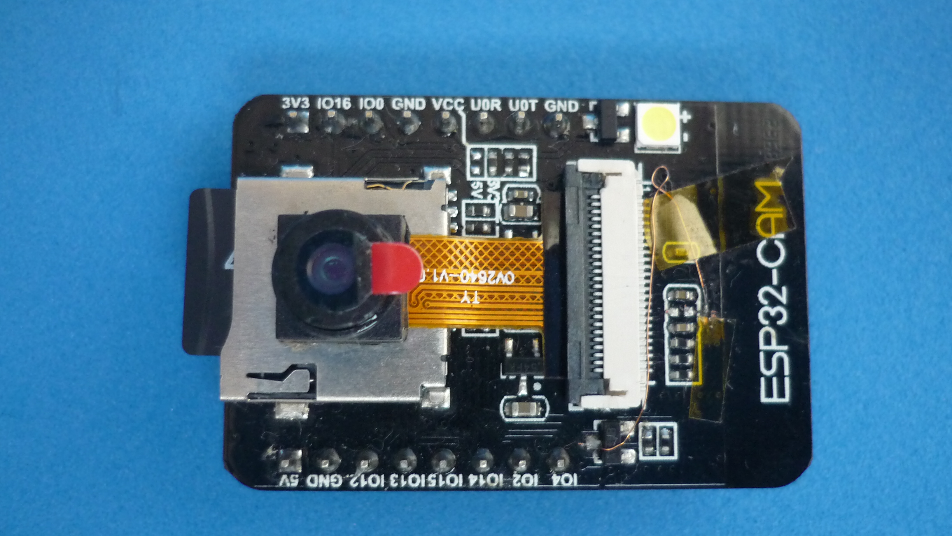
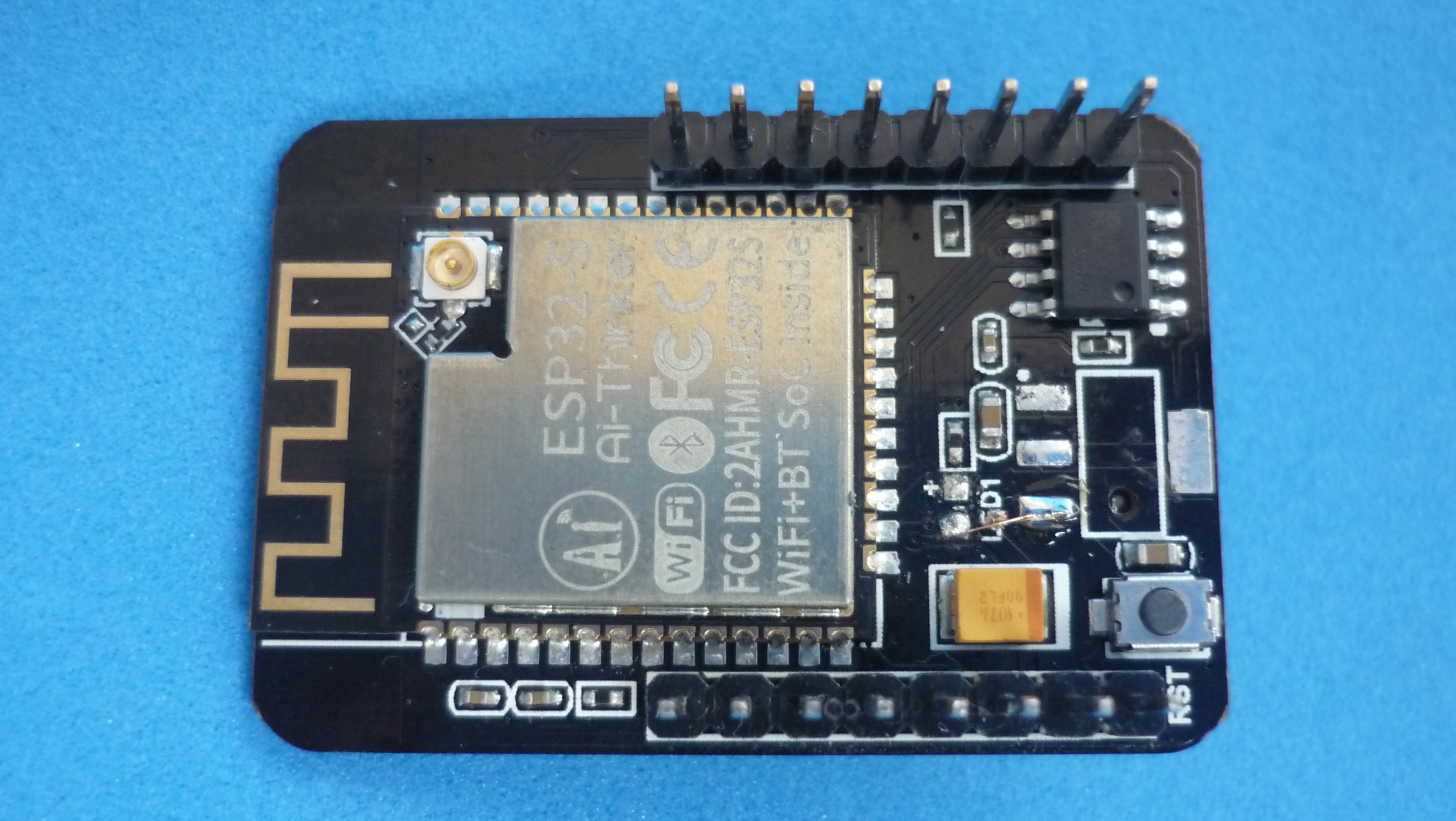
An ESP32-CAM module is a low-cost device based on ESP32-S module, an OV2640 image sensor and Micro SD slot. The module is not designed for low energy consumption, however, after some tweaks, the power consumption can be lowered to a level that is usable for short periods of time, powered by solar energy. The project presented here is a reasonably robust, dust-resistant and waterproof experimentation platform, using commercial off-the-shelf components. Ideal for outdoor usage.

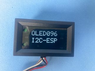
Key component: ESP 32 CAM
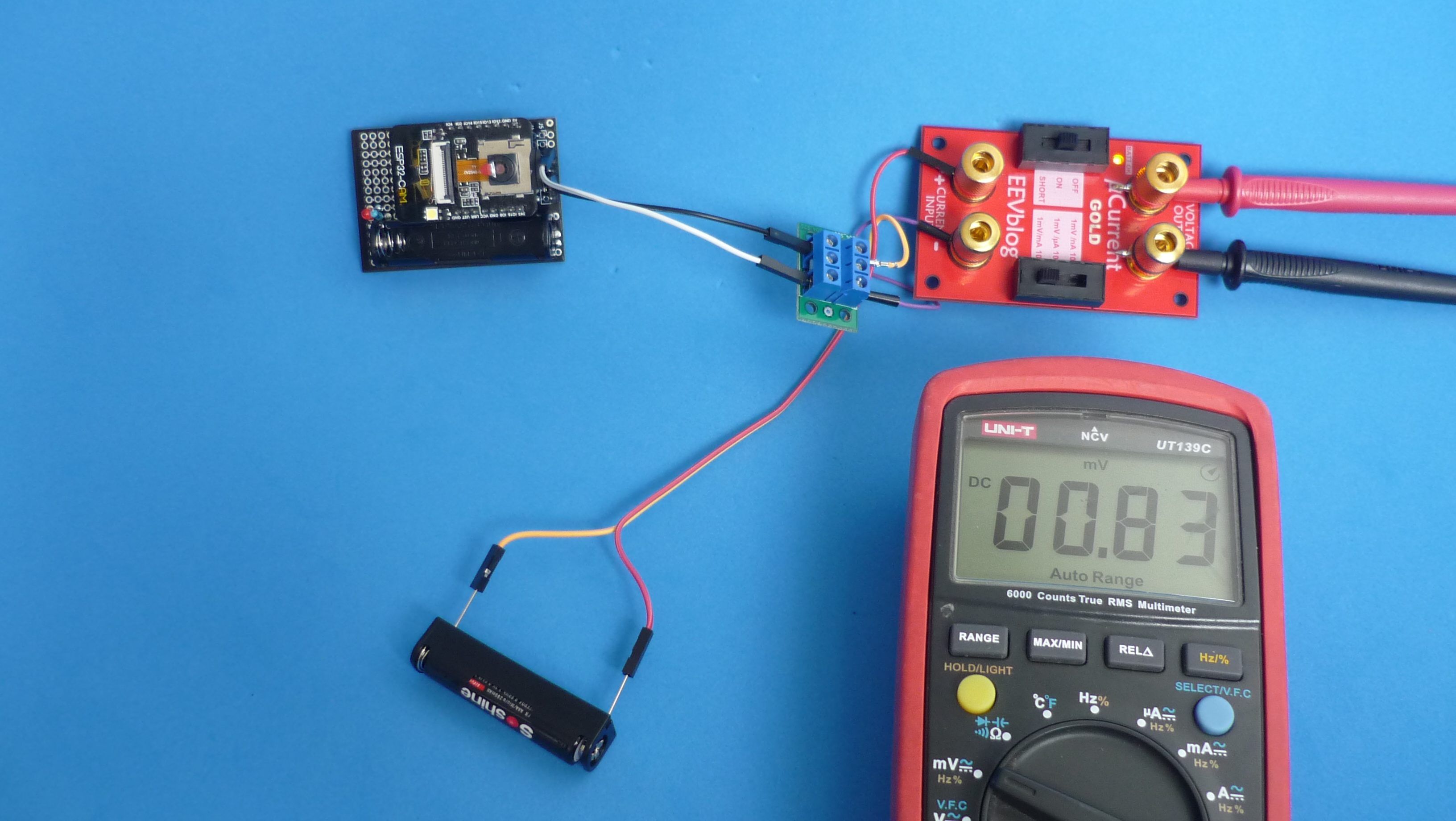
Lowering power consumption
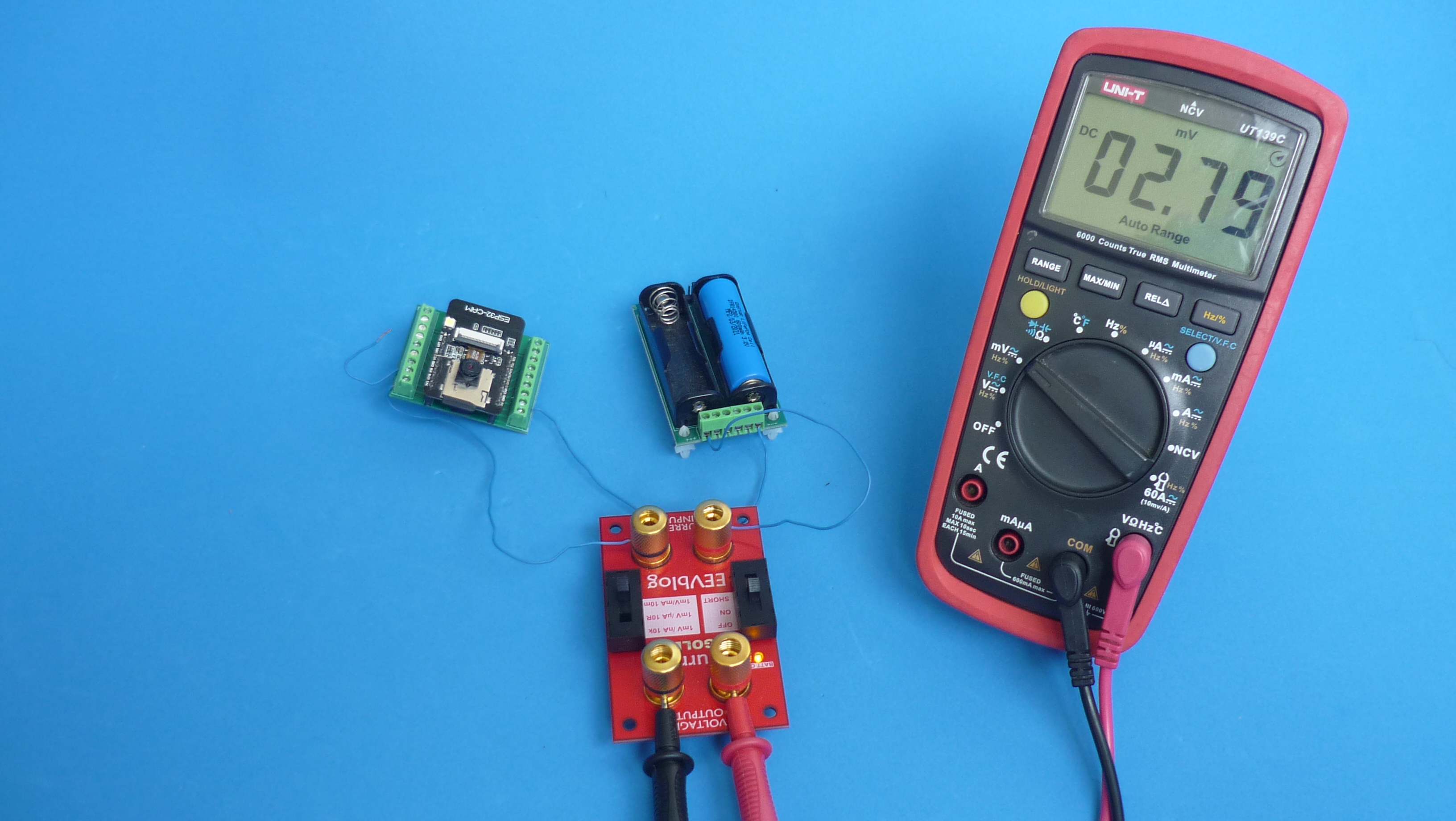
ESP32-CAM wasn’t designed to be a low power device. Without modifications, deep sleep current measured was 2.8 mA, it leaves much to be desired.
Some people on the Internet already ventured in the following modifications:
- Removed 5 V to 3 V voltage regulator, the camera will be powered directly from a 3.2 V LiFePO4 battery.
- Break trace that powers the camera from 3.3 V and wire to MOSFET Q2 who switches on 2.8 V and 1.2 V voltage regulators.
- Remove onboard led and wire GPIO33 to 5 V pin (this pin is already isolated after regulator removal) to use it externally.
These modifications lowered deep sleep current to 0.8 mA, which is scandalous for a low power device, however, is a substantial advance from the 2.8 mA without modifications.
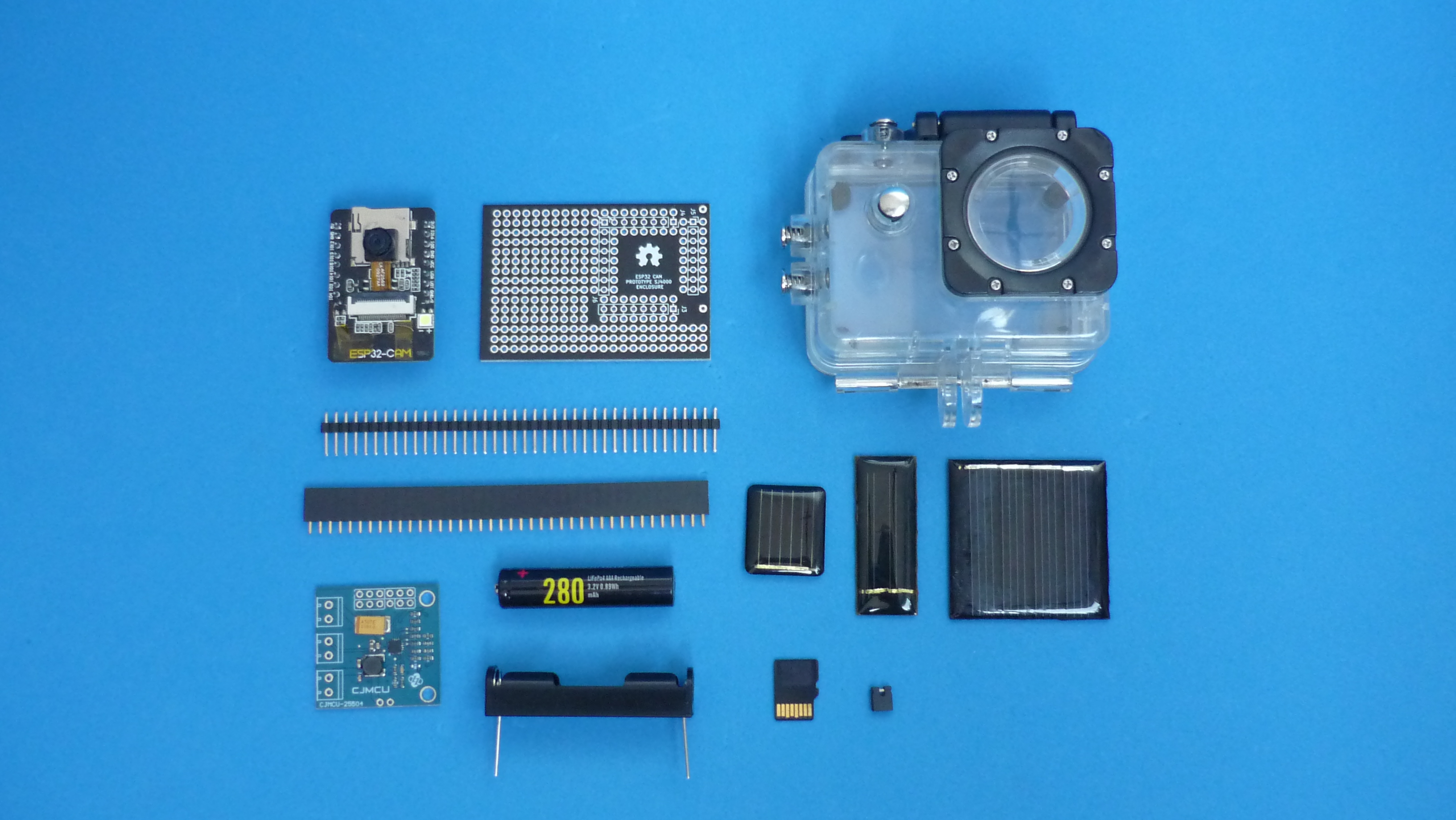
Bill of materials
| Printed Circuit Board | Buy link | Source files repository |
|---|---|---|
| ESP32-CAM prototyping board for sport cam enclosure | buy it | esp32cam-proto-sportcam |
| Software | repository |
|---|---|
| Sample Firmware takes photos and send them to a server using HTTP POST | download it |
| Sample Golang server for image upload via HTTP POST | download it |
| Optional component | Buy link | Datasheet |
|---|---|---|
| USB to TTL 3.3 V 5 V interface | buy it | usb-ttl-converter-3-3v-5v.pdf |
| Digital LCD Lux meter | buy it | digital-lcd-lux-meter.pdf |
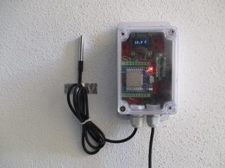
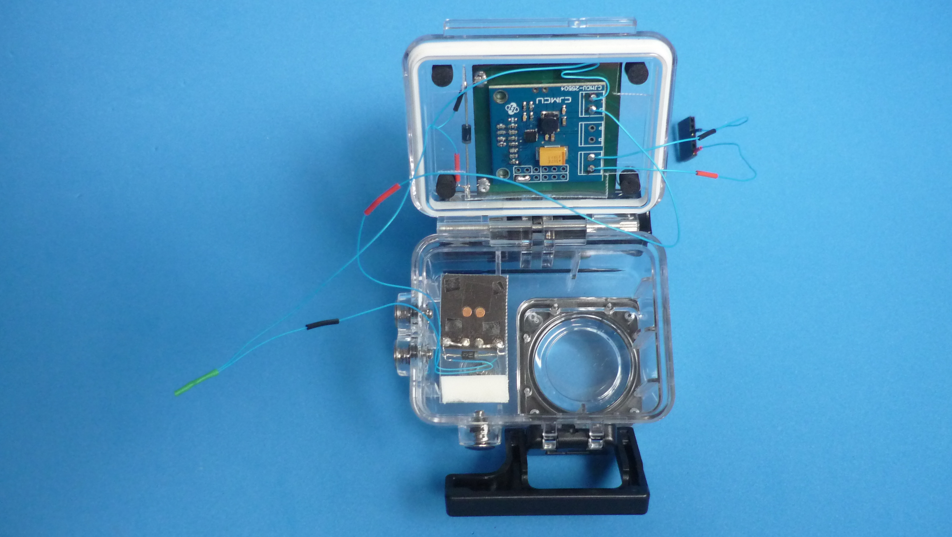
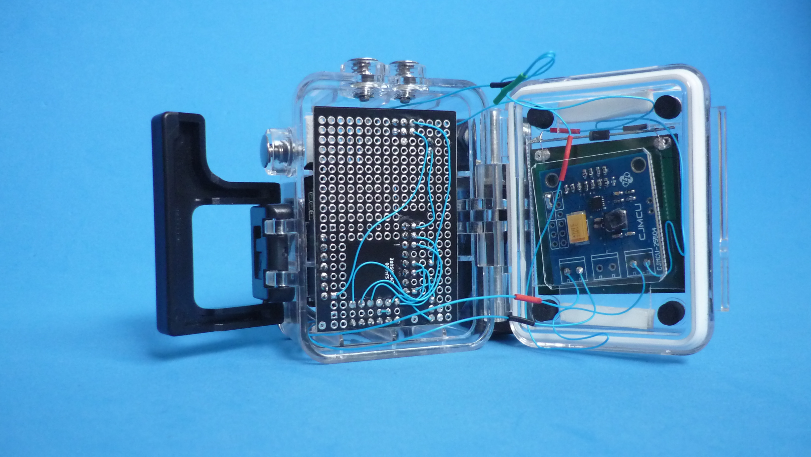
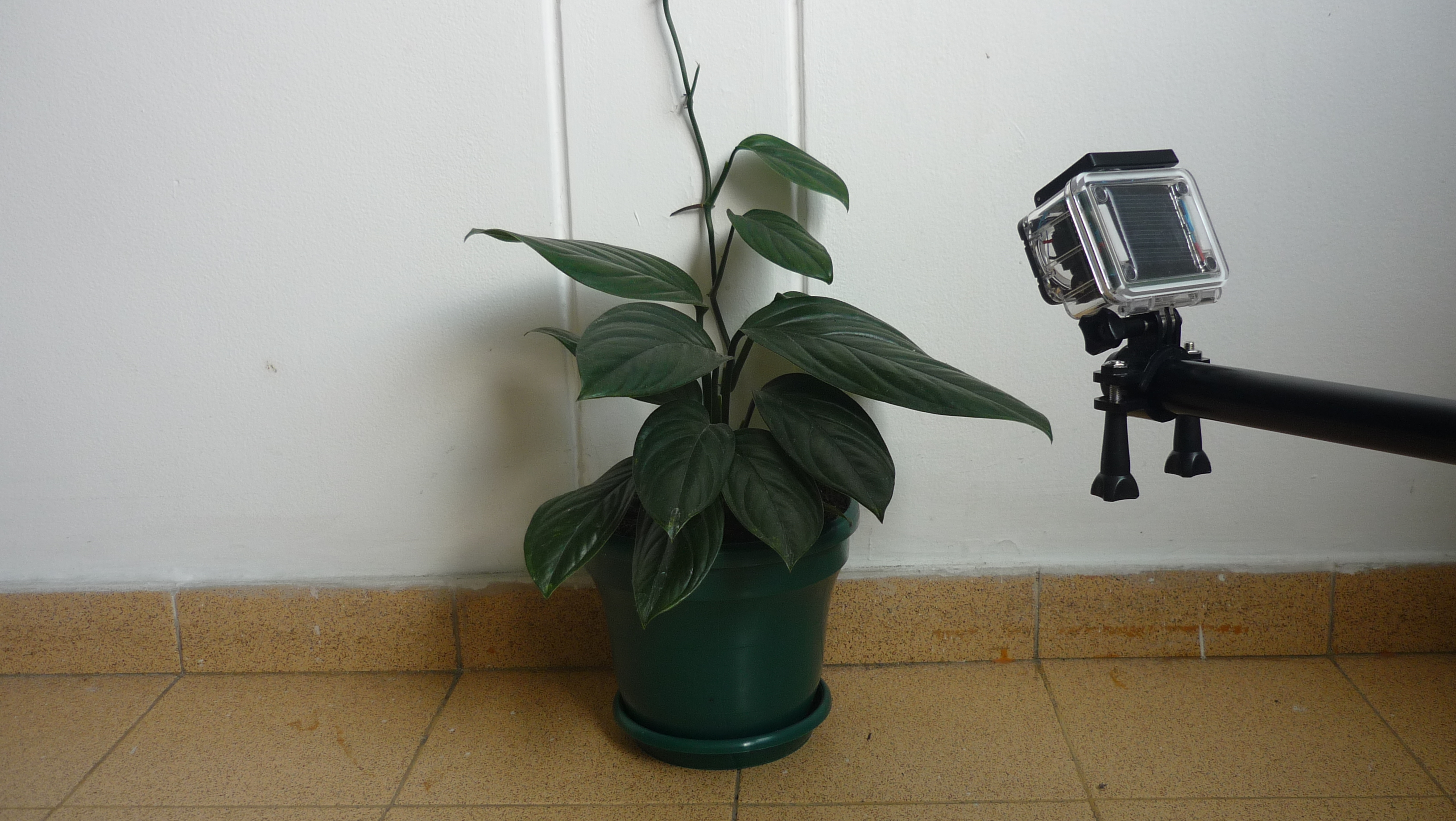
Assembly
The basic platform consists of a waterproof enclosure for sport cam and a printed circuit board with the appropriate size to fit inside.
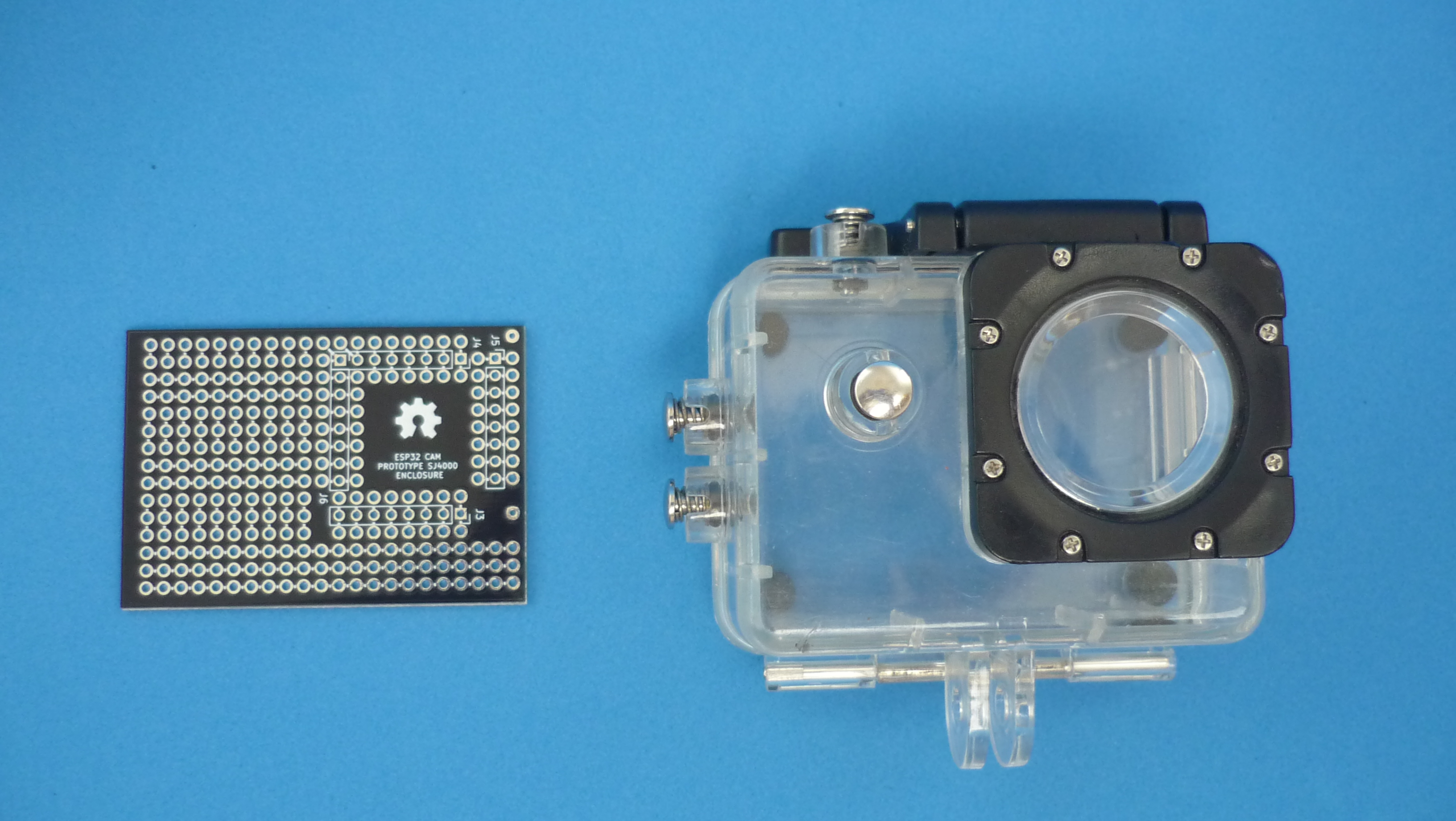
The proposed enclosure is pretty common, easy to find and inexpensive. Opens and closes without screws and has a mounting point where different mounting accessories can be installed.
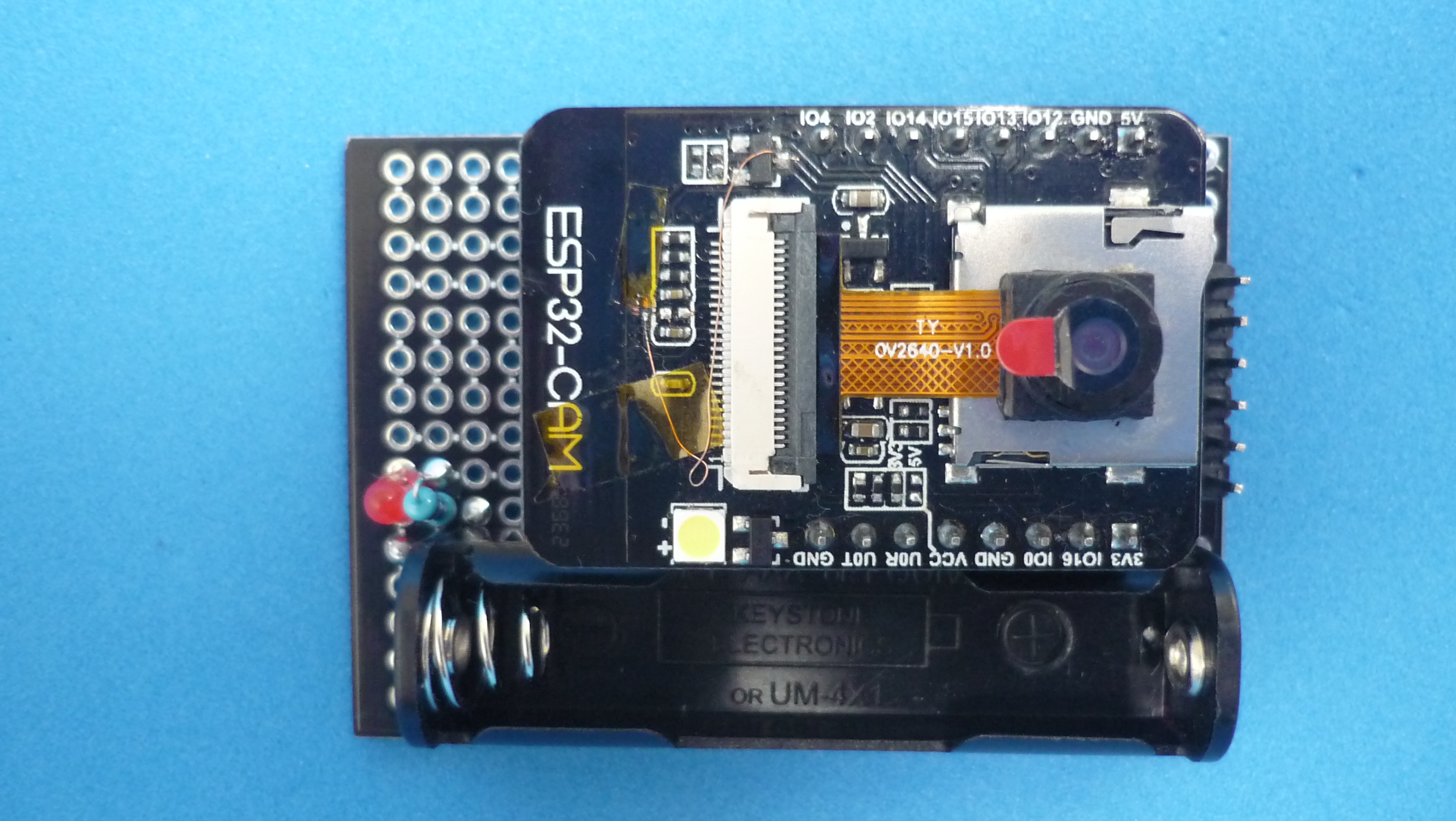
The printed circuit board was designed to place ESP32-CAM near the window where the camera lens was to be located. The module can be positioned in two different orientations to maximize area, depending on the selected components.
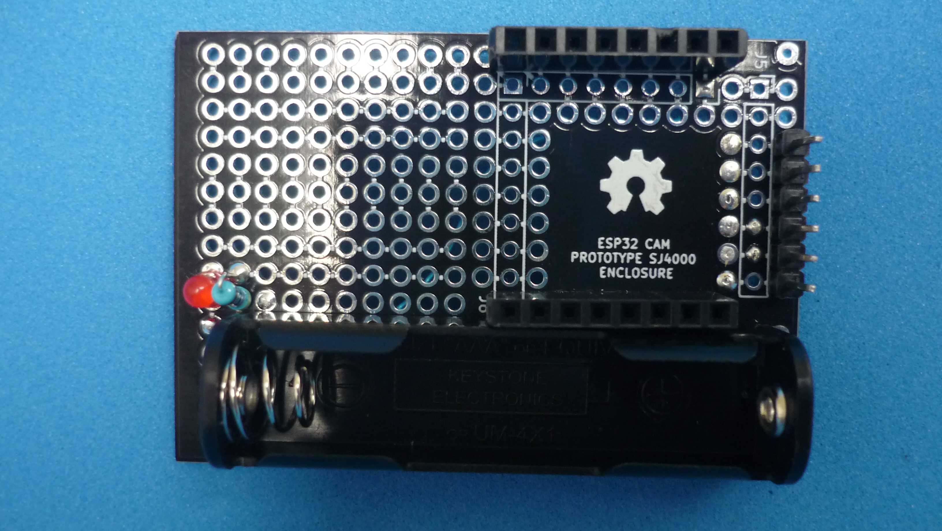
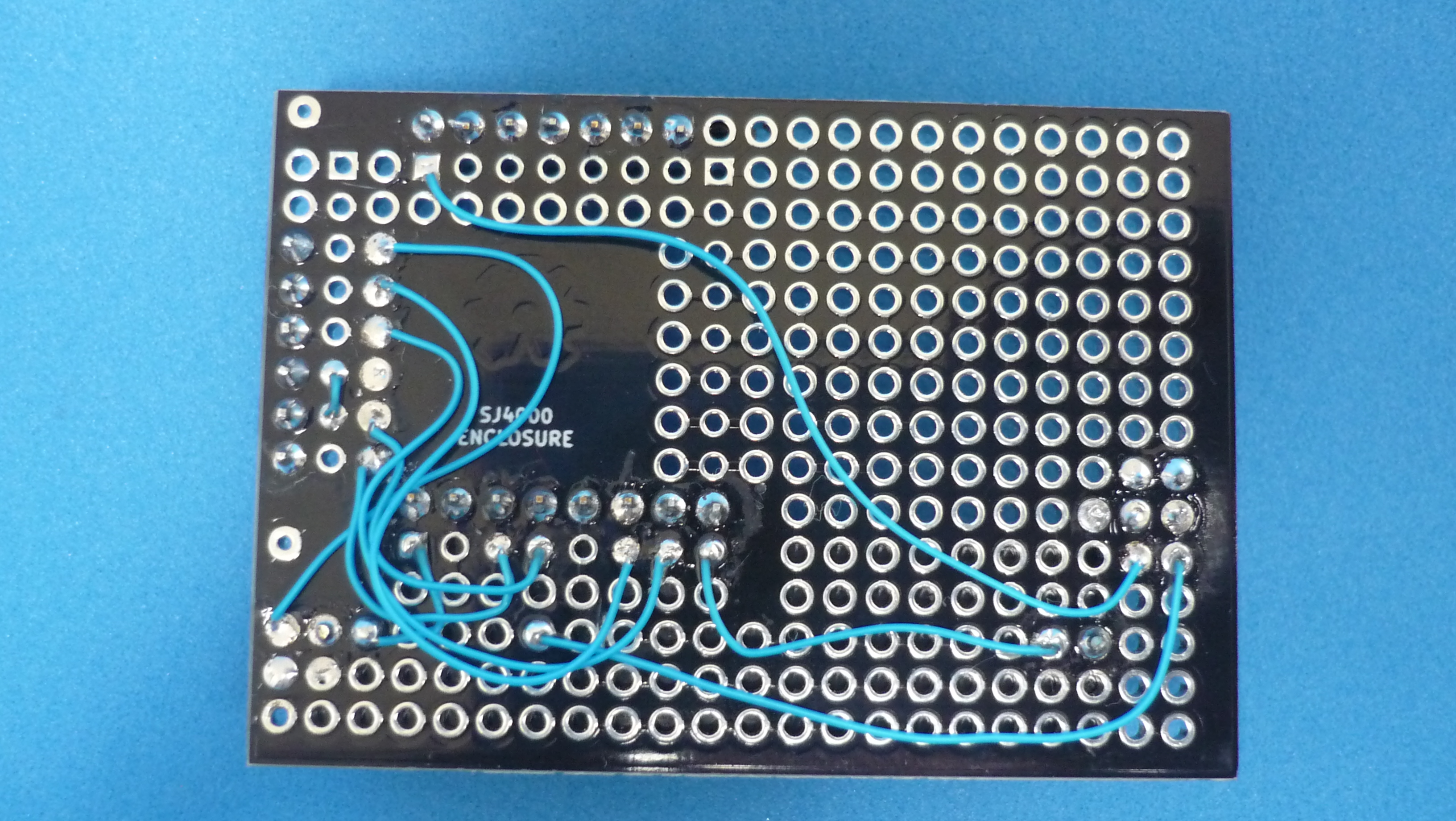
AAA battery clip added, female connectors to plug/unplug module easily and header pins for programming, because the board does not have such circuitry. Also, a red LED for debugging purposes was added.
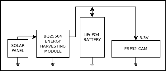
Energy harvester
The camera gets its energy from solar panels installed inside the enclosure, which means that the area available is small, so a way to maximize its efficiency is needed. A harvesting module based on BQ25504 chip was used. This device boosts solar panel voltage and is able to do that with voltages down to 130 mV!, is therefore able to supply current for storage in the battery, even without direct light hitting the panel.
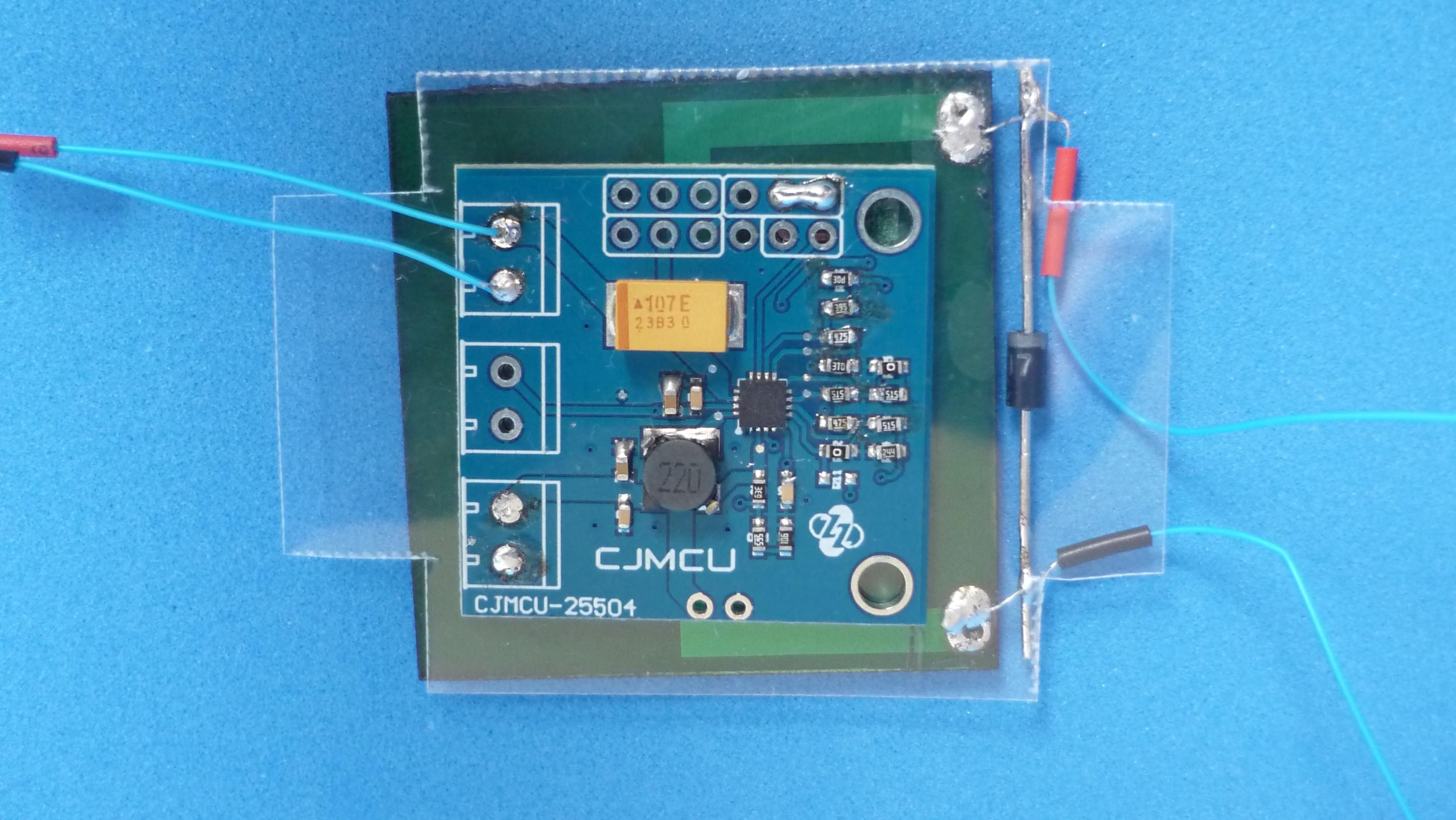
The module also works as a battery charger with over voltage and under voltage protection. In order to set voltage values, some resistors must be modified. The module’s manufacturer provides a spreadsheet to make the process easier.
Because the enclosure is transparent, it is possible to put a few solar panels in various places inside, and wire them in parallel or series. Maybe some diodes will be required to not lose a lot of efficiency when some panels are shaded.
Another important function of the energy harvesting module is the ability to output a VOLTAGE OK SIGNAL, so the MCU could be kept in reset state when the battery voltage is too low to operate.

Energy budget
Warning: Some data and procedures will be simplified to yield simpler and faster results!
ESP32 draws about 200 mA at 3.3 V to send data over Wi-Fi, which is equivalent to 0.66 W. A 40x40 mm solar panel that fits inside the aforementioned enclosure yields around 65 mA at 2 V at full sun, which is equivalent to 0.13 W.
With this data, it is clear that it is not possible to use ESP32 sending data over Wi-Fi continuously with that panel, even in full sunlight.
To deal with this problem, two things are needed: a storage element, and the use of the ESP32 module in non continuous (duty cycled) mode.
The module in deep sleep mode draws about 0.88 mA at 3.3 V, which is equivalent to 0.003 W. Assuming 12 hours of daylight, it will take an average of 0.006 W average per day, just to keep the module energized up in sleep mode. If the pair panel/harvester can yield an average of 4.6% of the maximum power of the solar panel at full sun, it is enough to keep energized the ESP32 in deep sleep mode for a very long time (until battery degradation!).
Assuming 100.000 Lux as a full sun and 100% of the 40x40 mm solar panel power as 0.13 W, it is estimated that the average irradiance required per day to keep the ESP32 energized in deep sleep is around 4600 Lux.
How much energy is required to take a picture and upload it over the internet?
After waking up from a deep sleep, it takes about 4 seconds for the ESP32 to take a picture, store it in the SD card, and bring it online. The average power consumption of these 4 seconds is 200 mA at 3.3 V. The current to be accumulated for 12 hours to is:
ESP 32 Cycle:
200 mA x 4 S
It is needed:
? mA x 12 H
? ma x 12 (3600) S
? ma x 43200 S (Approximating to 40000 to make calculations easier)
factor = 4 S / 40000 S = 0.0001
200 mA * 0.0001 = 10 uA
It is required an average of 10 uA for 12 hours to take a picture and send it to a server, which is perfectly feasible in the outdoors, even on cloudy days.
Finding the relation between Lux and output power of the 40x40 mm and 0.13 W solar panel.
100.000 Lux => 0.13 W
0.77 Lux => 1 uW
10uA * 3.3V = 33 uW
(0.77 Lux /uW ) 33 uW = 25.4 Lux (Approximating to 26 Lux)
It will take an average of 26 Lux per day to take a photo and send it over Wi-Fi
In short, to take at least one photo a day and send it over Wi-Fi, it will take a daily average of 4600 Lux + 26 Lux = 4626 Lux. For two pictures a day it will take a daily average of 4652 Lux, and so on.
If a smaller panel is used, such as the 30x25 mm in the front of the camera, whose power is about a quarter of that installed on the back, the irradiance should be 4 times stronger.
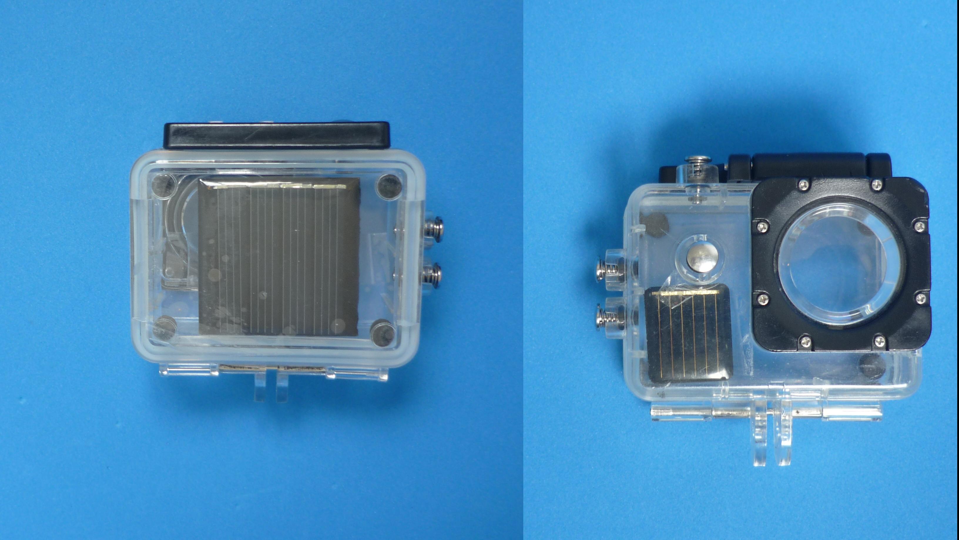
To use the camera with such a small panel, a lot of light is required, especially direct light.
Firmware and Software
The firmware released here does the following things: take a picture and store in the Micro SD card, then send it over Wi-Fi to a server doing a multipart HTTP POST request and then, enters deep sleep for X amount of seconds before starting the cycle again. The code could serve as a starting point in the creation of a more robust application adapted to individual needs.
On the server side, there is a small app written in Golang, which listens HTTP POST requests and receives the images sent by the ESP32-CAM and stores them in a local folder. This app should run on a PC, or a Raspberry Pi in the same LAN of the ESP32-CAM. Due to being a basic starter example, there is no authentication method developed, so it is not recommended for deploying in a public server in the Internet.
To program the module, a USB to TTL serial converter is needed, because the module hasn’t an onboard chip for that task. In addition, GPIO0 should be tied to GND during programming.
GPIO33 was freed from the onboard LED and wired externally. The supplied firmware uses it for debugging, but it may be used for other purposes like:
- ADC for battery voltage measurement
- Set up as an RTC pin to wake up the MCU from deep sleep, i.e., PIR sensor
- Wire to a pushbutton to make local changes without a computer or Wi-Fi connectivity
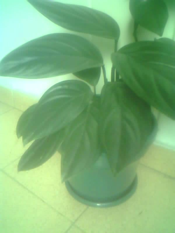
Results
Image quality isn’t great, which was expected due to the cost of the module. Quality could be improved, modifying several parameters of the chip depending on the specific lighting conditions. The image shown below was uploaded automatically by the module through Wi-Fi to a Raspberry Pi where the Golang upload server was running
Possible improvements
Since firmware and upload server are very basic examples, there are some tasks proposed to the reader like:
- Wi-Fi manager to set up credentials without reprogramming.
- Implement some form of authentication when communicating with the server.
- A mechanism to change the deep sleep time, image settings, etc. from the server on every picture exchange.
- Develop an RTC-based scheduler to take pictures on specific dates.
- Use of a better Wi-Fi antenna (external to the module, but placed inside the enclosure), and place it in a place with less obstructions. Certain changes are needed in the components near the U.FL connector.