Ground station for LoRa satellites
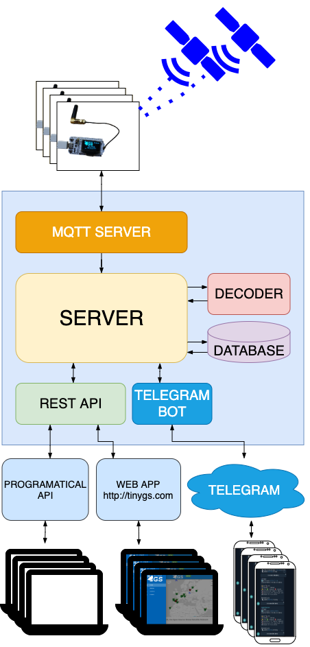
The arrival of small satellites that used LoRa for telemetry data has meant that less technically qualified persons, with a very low budget, can receive their signals.Thanks to TinyGS, there is now an open network of distributed ground stations, and more stations can be built to increase their coverage.The project presented here is a reasonably robust, dust-resistant and waterproof implementation of TinyGS ground station, using commercial off-the-shelf components. Ideal for outdoor usage
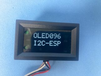
Key component: Heltec WiFi LoRa kit 32 v2 433mhz
Why?
The idea of using LoRa for satellite communications became obvious to many people for the following reasons:
- Uses unlicensed ISM band
- Availability of ready to use, low cost, easy to find electronic modules.
- Very long range, and low power communications
- Reception possible with very low level signals -120dBm
The last point is very important, since many commercial antennas can be used (homemade too!), even if they aren’t very efficient, are enough to receive signals. This was the Achiles’ heel of satellite communications until now
What is the project about?
This project is about a gateway between the Internet (WiFi) and LoRa @433Mhz using as much as possible of commercial off-the-shelf components, so not much expertise needed for assembly. The final key consists in downloading TinyGS firmware which allows something like:
- Download automatic firmware updates (OTA)
- The receiver will tune automagically to the nearest satellite in the sky
- Configuration of parameters using the local web interface
Bill of materials
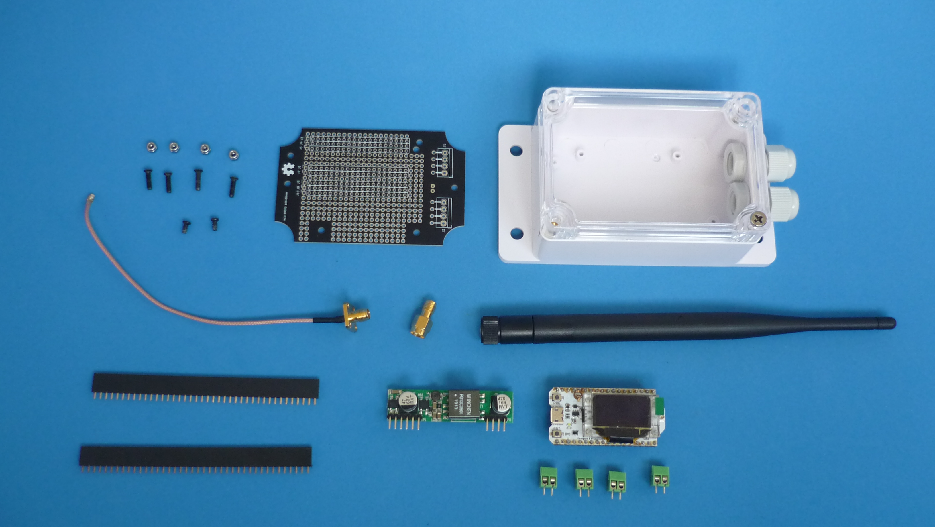
| Component | Buy link | Datasheet |
|---|---|---|
| Heltec Lora Kit 32 V2 433MHZ ESP32 | buy it | WiFi-LoRa-32-V2-433-470-510.pdf |
| RP-SMA flange to U.FL pigtail | buy it | Catalog_SMA.pdf |
| 433 Mhz antenna SMA | buy it | 433_MHZ_SMA_ANTENNA.pdf |
| Generic 100x68x50mm waterproof enclosure box “Sonoff” | buy it | SONOFF-IP66-waterproof-case.pdf |
| M2.5 countersunk screw phillips | buy it | M2-5_COUNTERSUNK_SCREW.pdf |
| M2.5 nylon lock nut | buy it | M2-5_NYLON_LOCK_NUT.pdf |
| M2.6 self-tapping B-type screw | buy it | M2.6x5-6-8-12mm.pdf |
| Screw terminal kf350 3.5mm 3 pin | buy it | KF350.pdf |
| Female header 2.54mm | buy it | FHA3-S1XX.pdf |
| 30 AWG wire wrap UL1423 PVDF | buy it | UL1423.pdf |
| PoE injector 48V 0.5A | buy it | PoE-injector-48V-05A.pdf |
| PoE Splitter D1398 module 5V 2A output | buy it | WC-PD13C050I.pdf |
| SMA Female To RP SMA Male adapter | buy it | SMA-Female-To-RP-SMA-Male-adapter.pdf |
| Silicone Sealant Neutral RTV | buy it | Neutral-cure-silicone.pdf |
| Waterproof silicone self fusing vulcanizing tape | buy it | Waterproof-silicone-self-fusing-vulcanizing-tape.pdf |
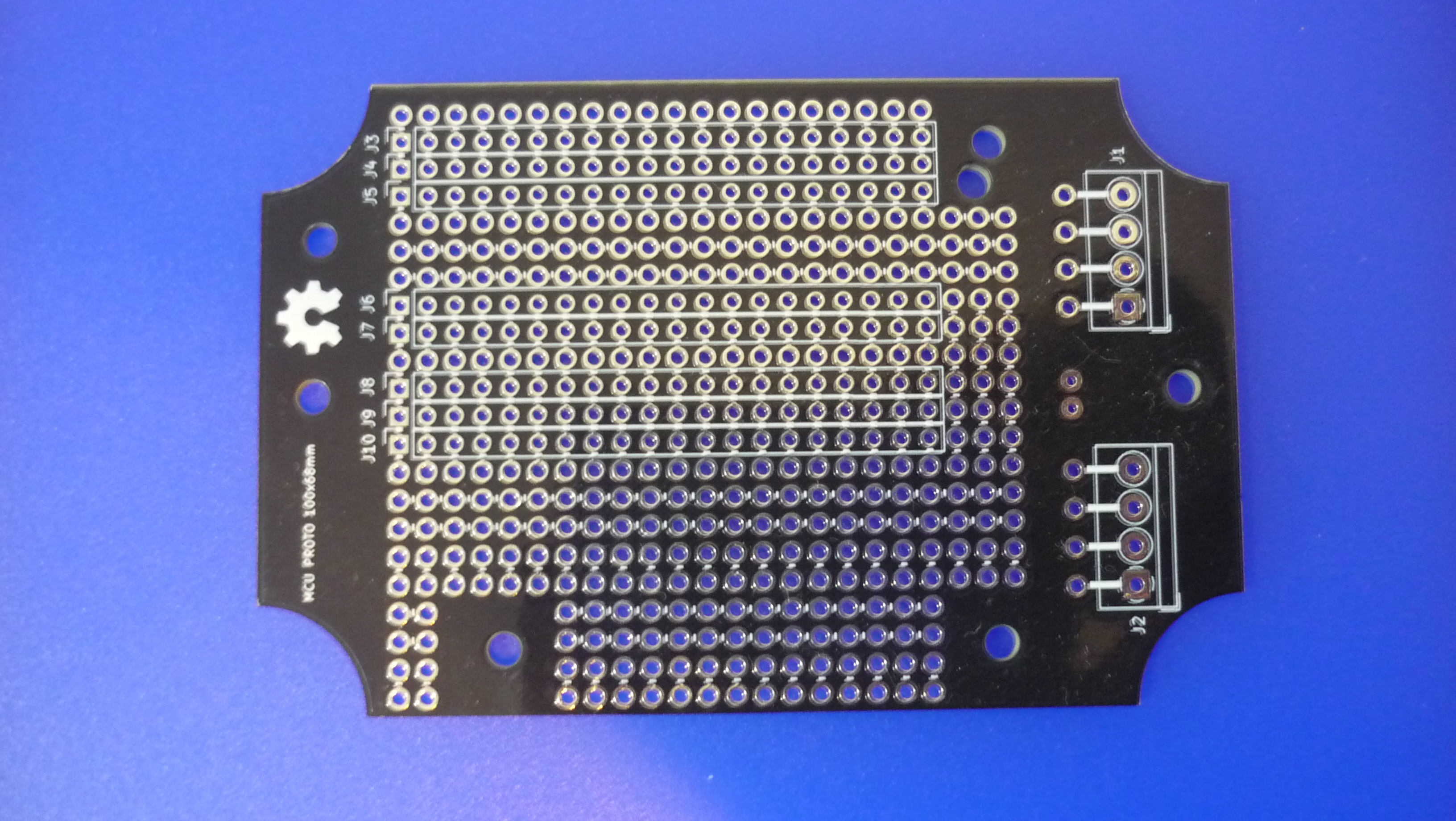
| Printed Circuit Board | Buy link | Source files repository |
|---|---|---|
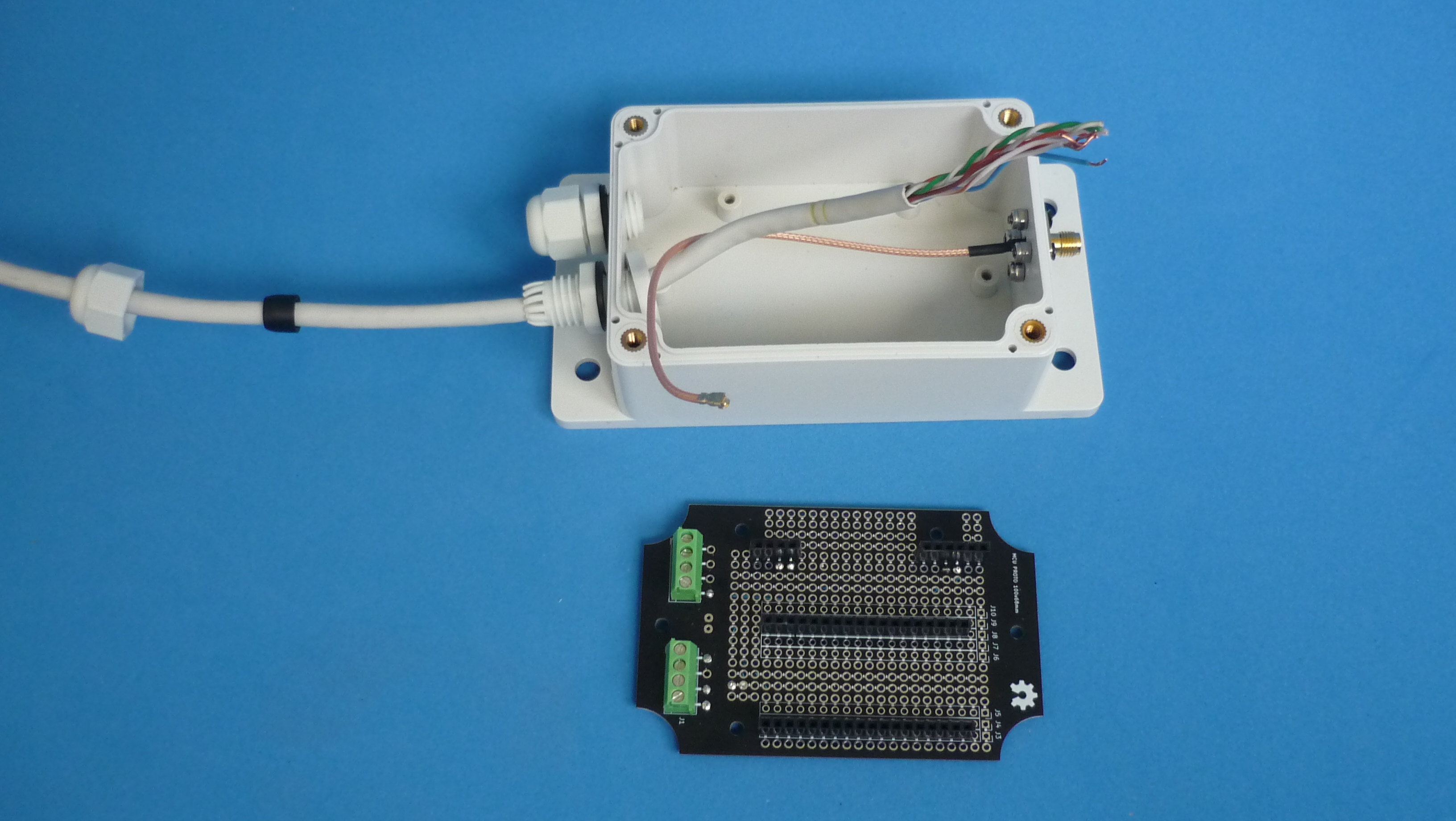
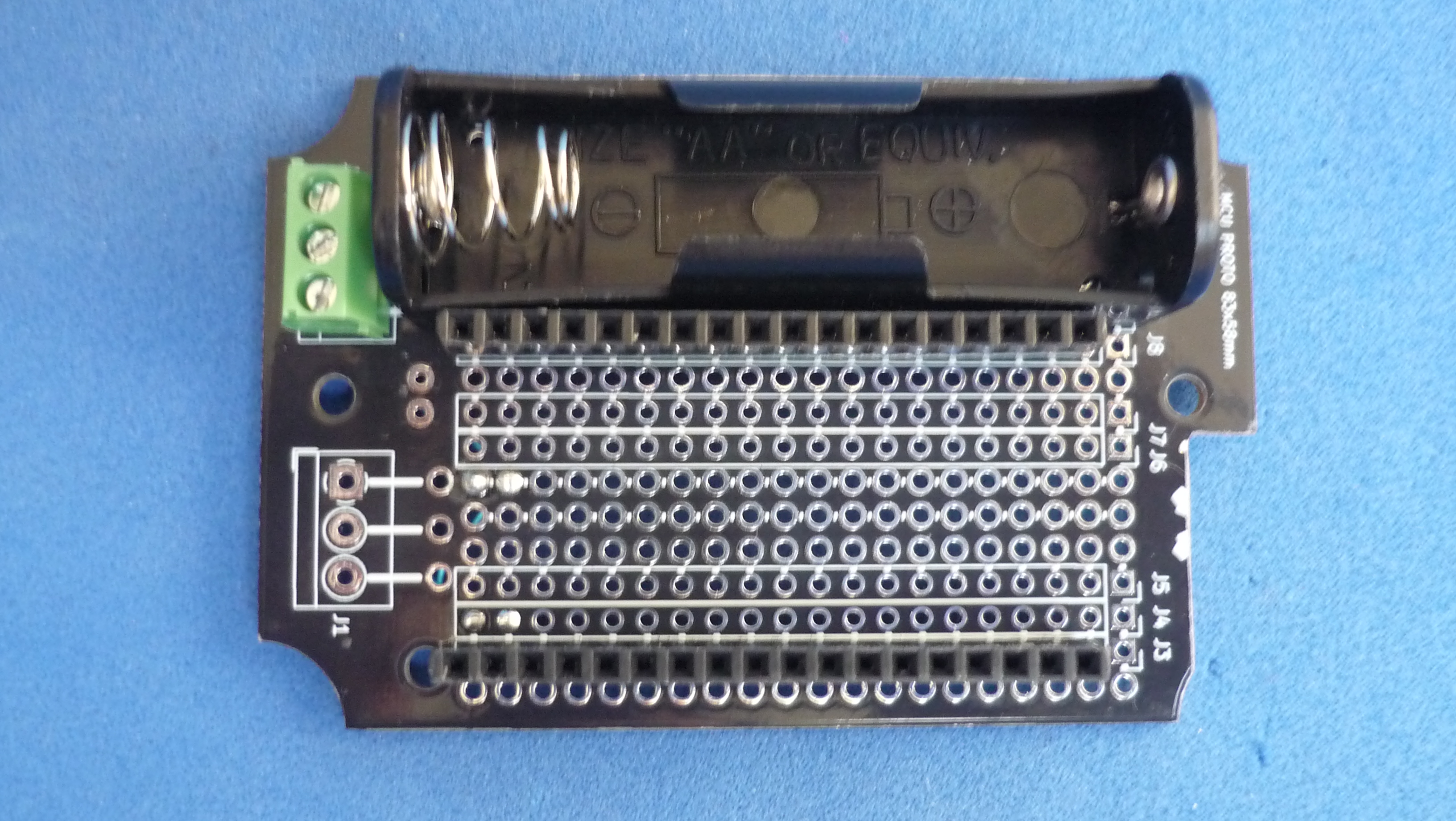
| Prototype circuit board for 100x68mm enclosure | buy it | mcu-proto-100x68mm |
| Software | repository |
|---|---|
| TingyGS Firmware | download it |
| Optional component | Buy link | Datasheet |
|---|---|---|
| Hand drill set mini 0.5-3mm | buy it | Hand-drill-set-mini.pdf |
Assembly:
This article is not intended to be a step-by-step assembly guide, it will attempt to explain briefly what to do next. Depending on the components obtained, some instructions and their sequence may change slightly.
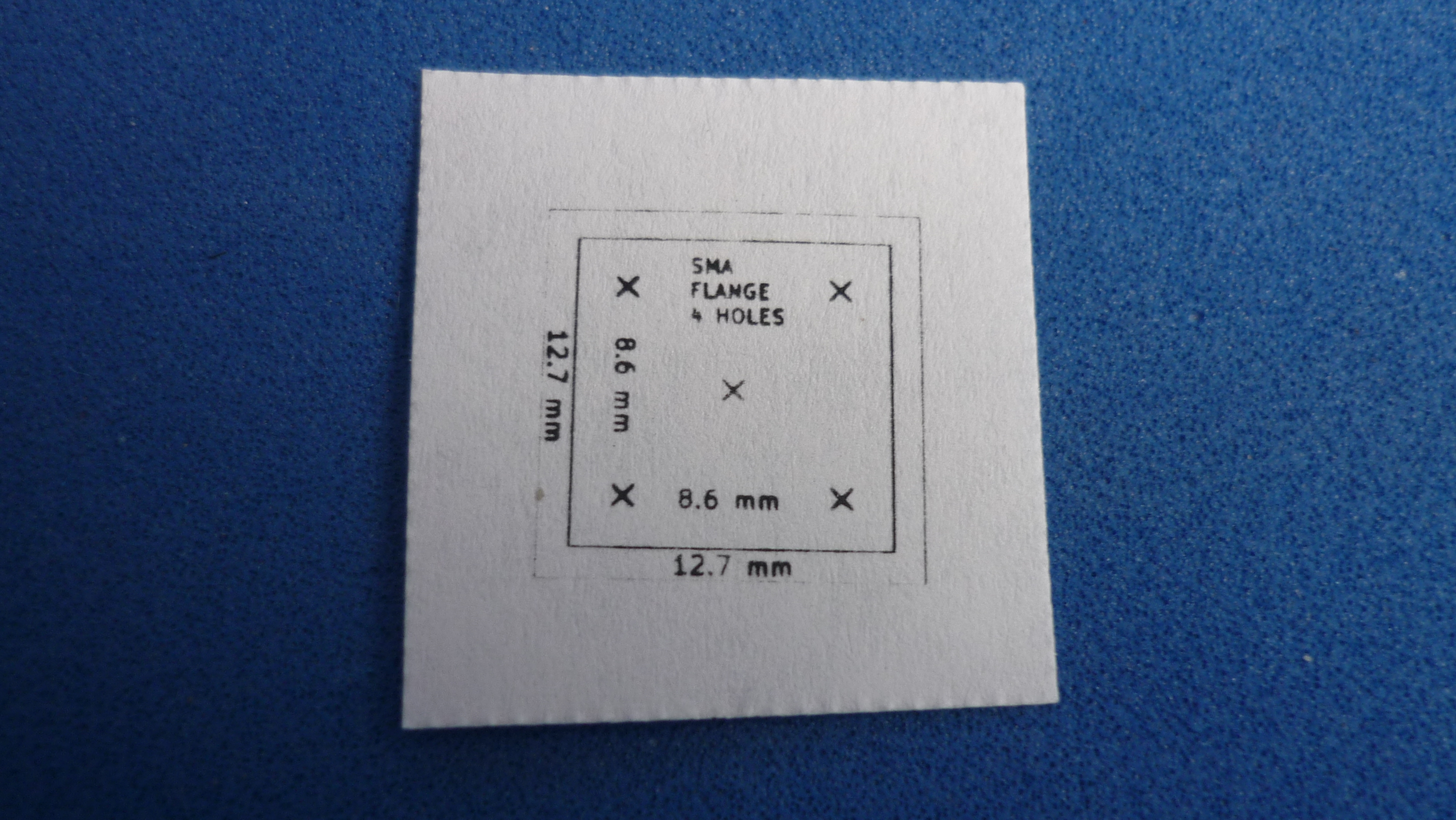
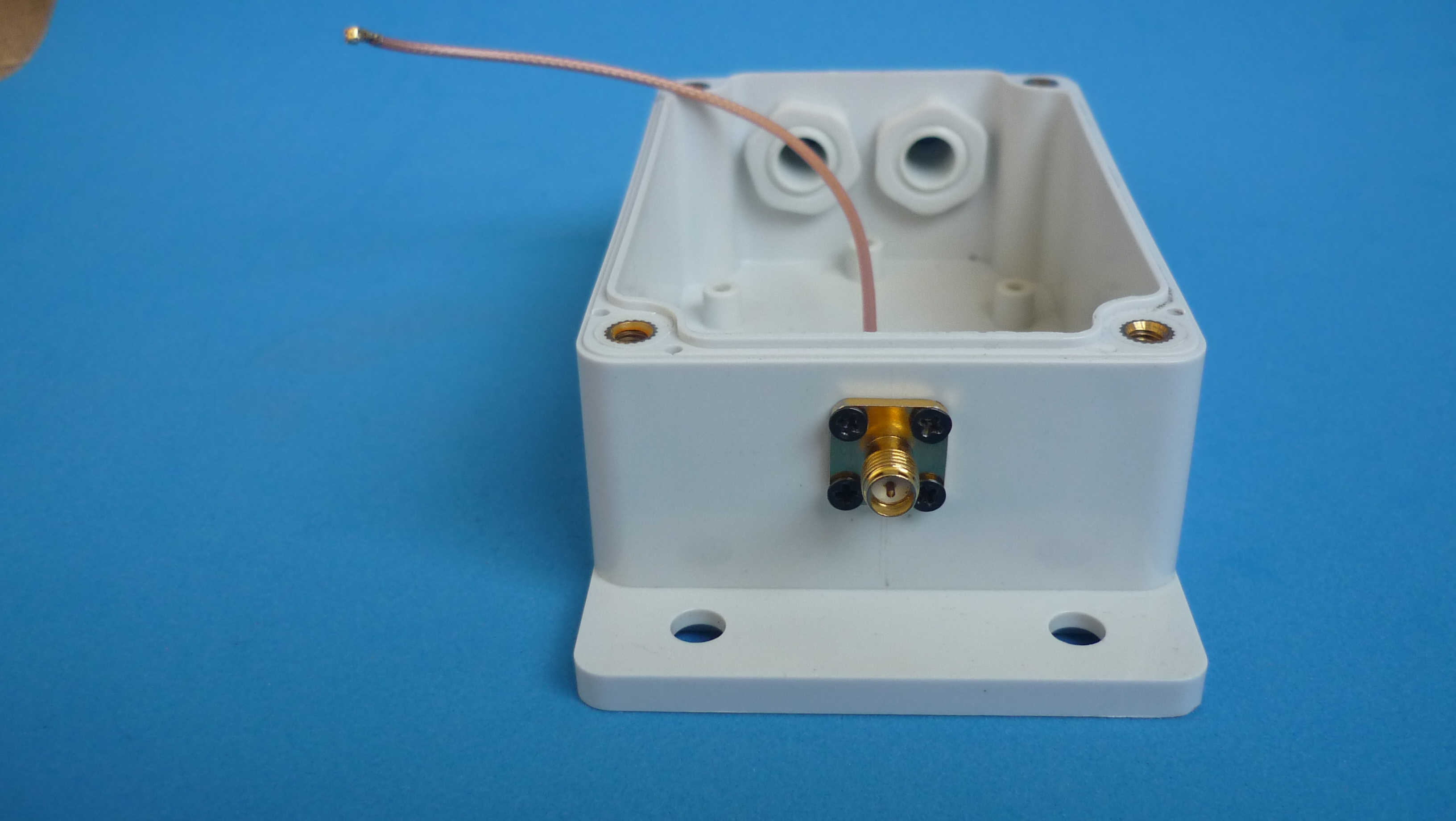
Antenna connector drillings:
-
Make 4 drillings with a bit slightly wider than 2.5 mm, that’s where the fixing screws will go.
-
Make another drilling in the middle with a bit slightly wider than 4 mm, that’s where the pigtail wire will go. The drill assistant template can be found here.
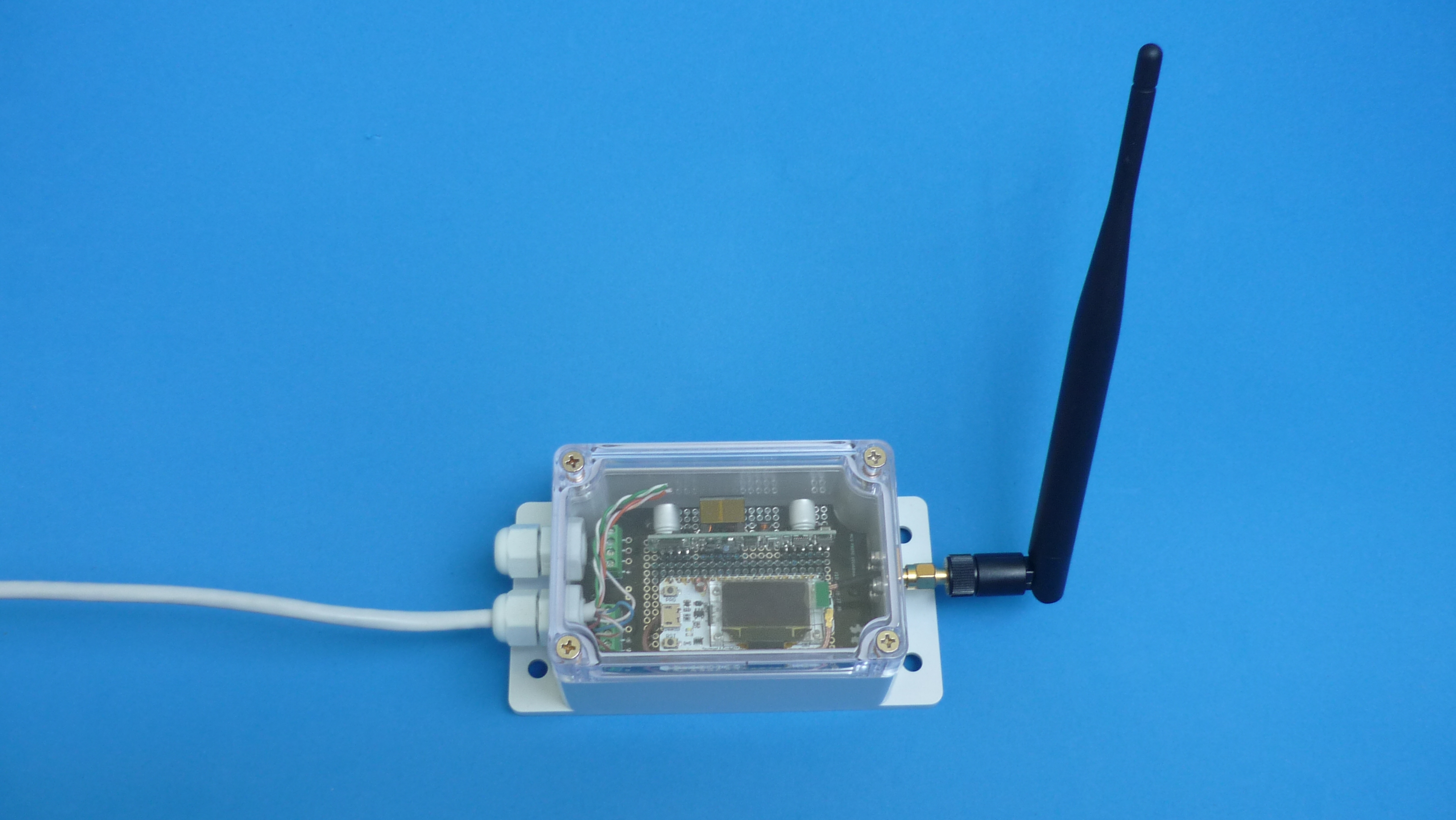
Connectors and wire soldering
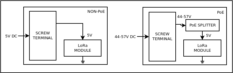
There are two options to power the station: using a simple 5V power supply or using a PoE adapter. The 5V power option requires less hardware, but is limited to a few meters of cable, however the PoE version requires a PoE injector, a PoE splitter inside the case, but it can be placed up to 100 meters away
-
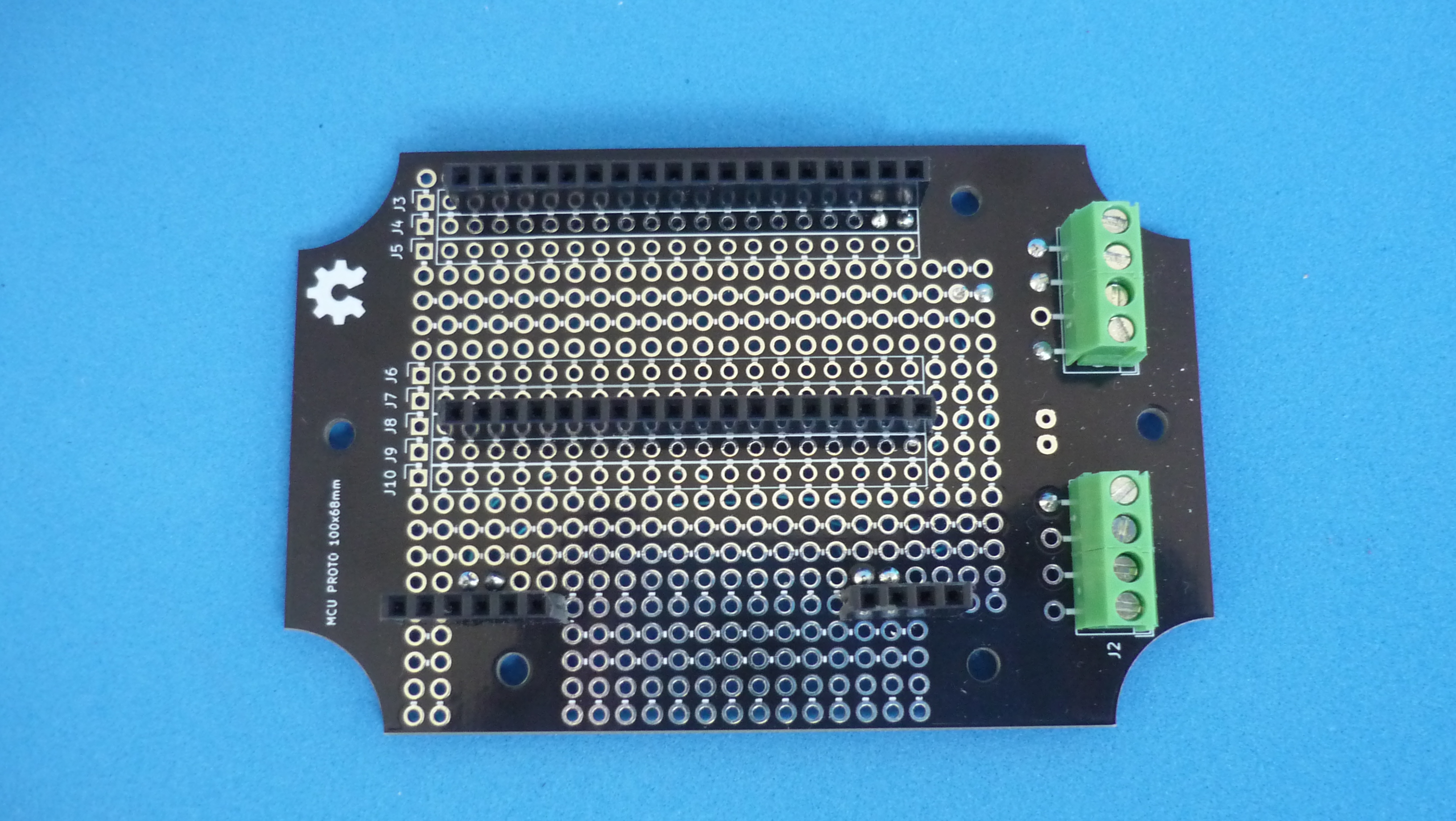
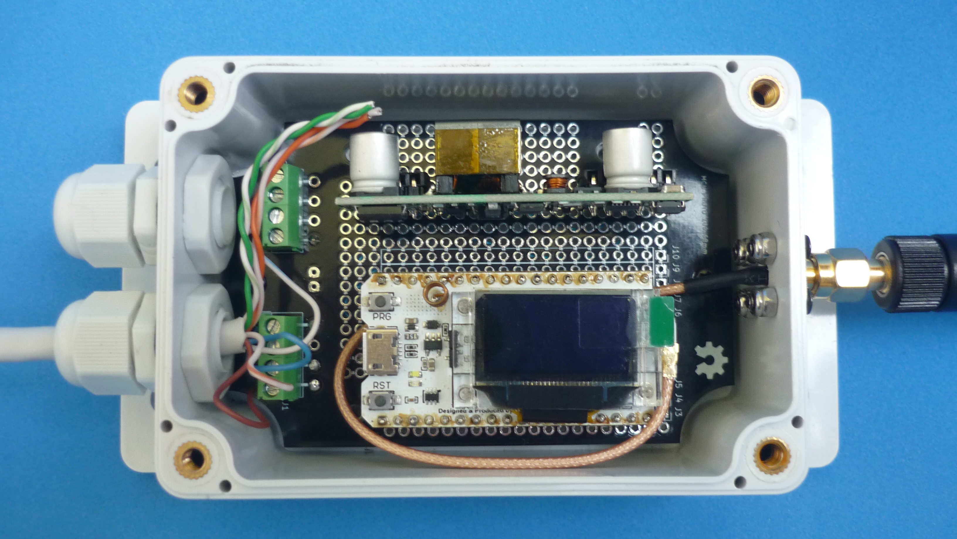
Solder LoRa module headers. This is not 100% necessary, because the module could be soldered directly to the board, however, using headers make it possible to disconnect the module at any time.
-
Solder PoE splitter module header (if used!)
-
Solder PCB screw terminals for ease of connection/disconnection of the power cable.
-
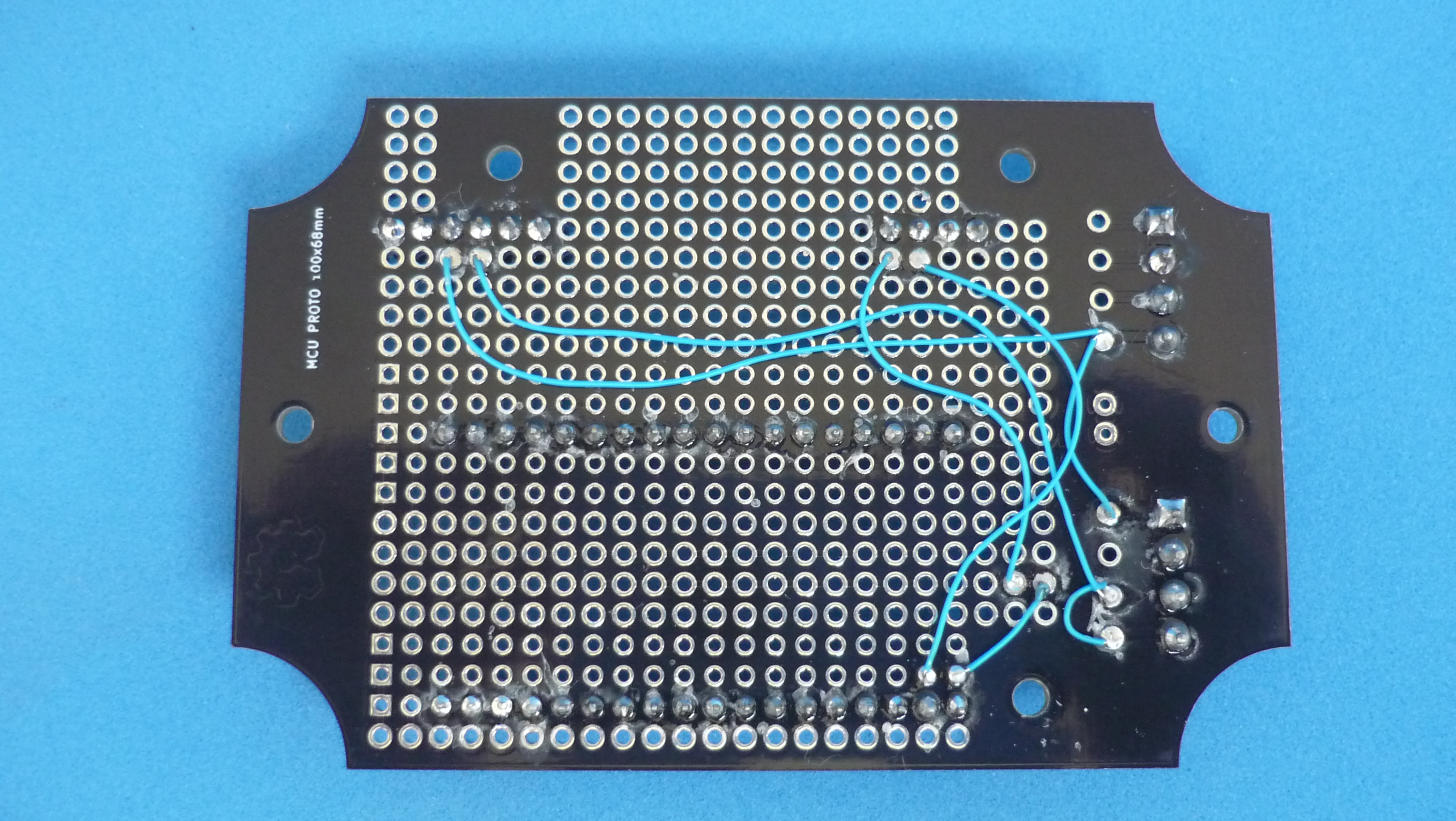
Solder the power wires under the board, using PVDF coated wire when possible, between the screw terminal pads and the PoE power pads and then to the LoRa power pads
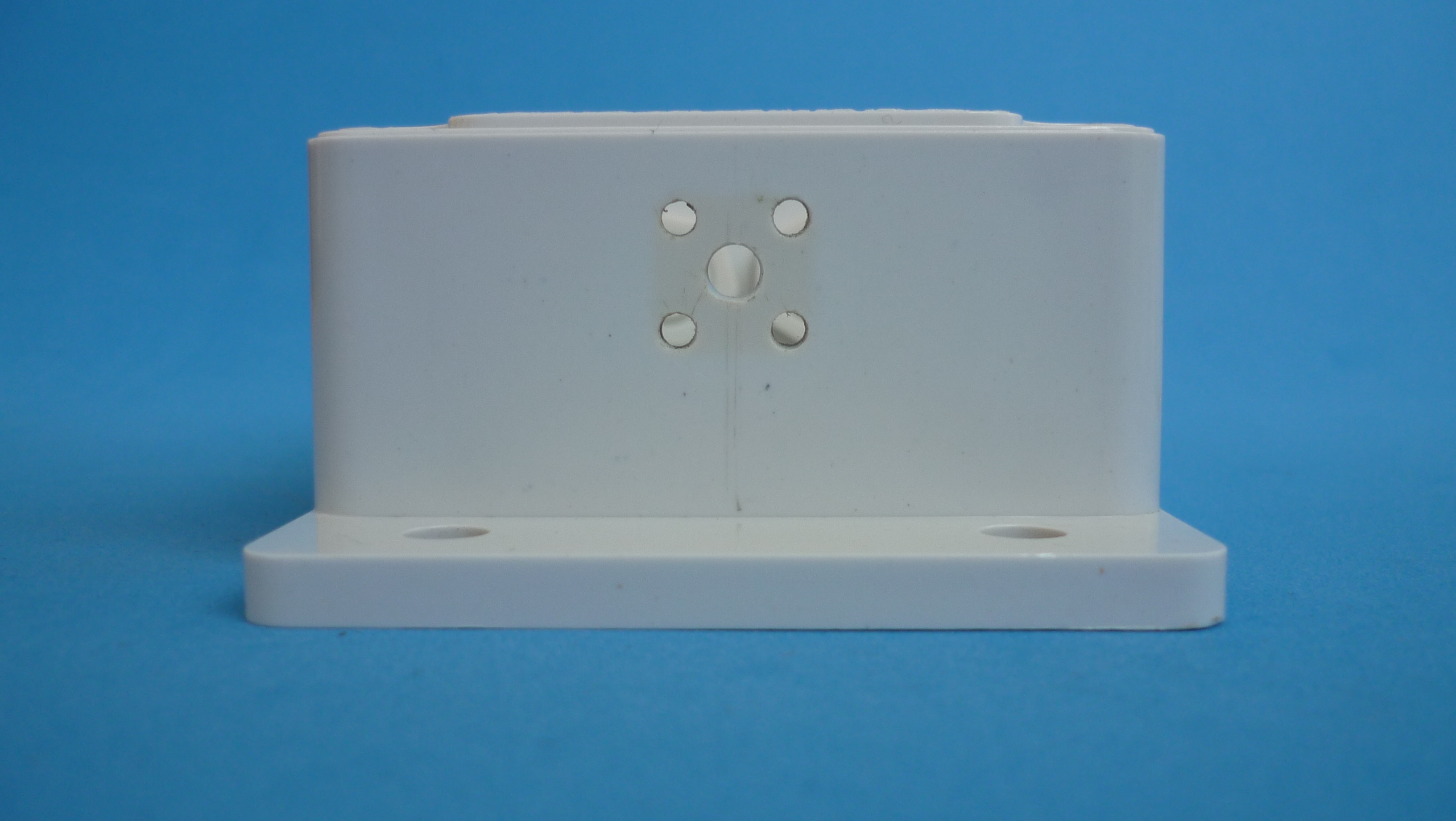
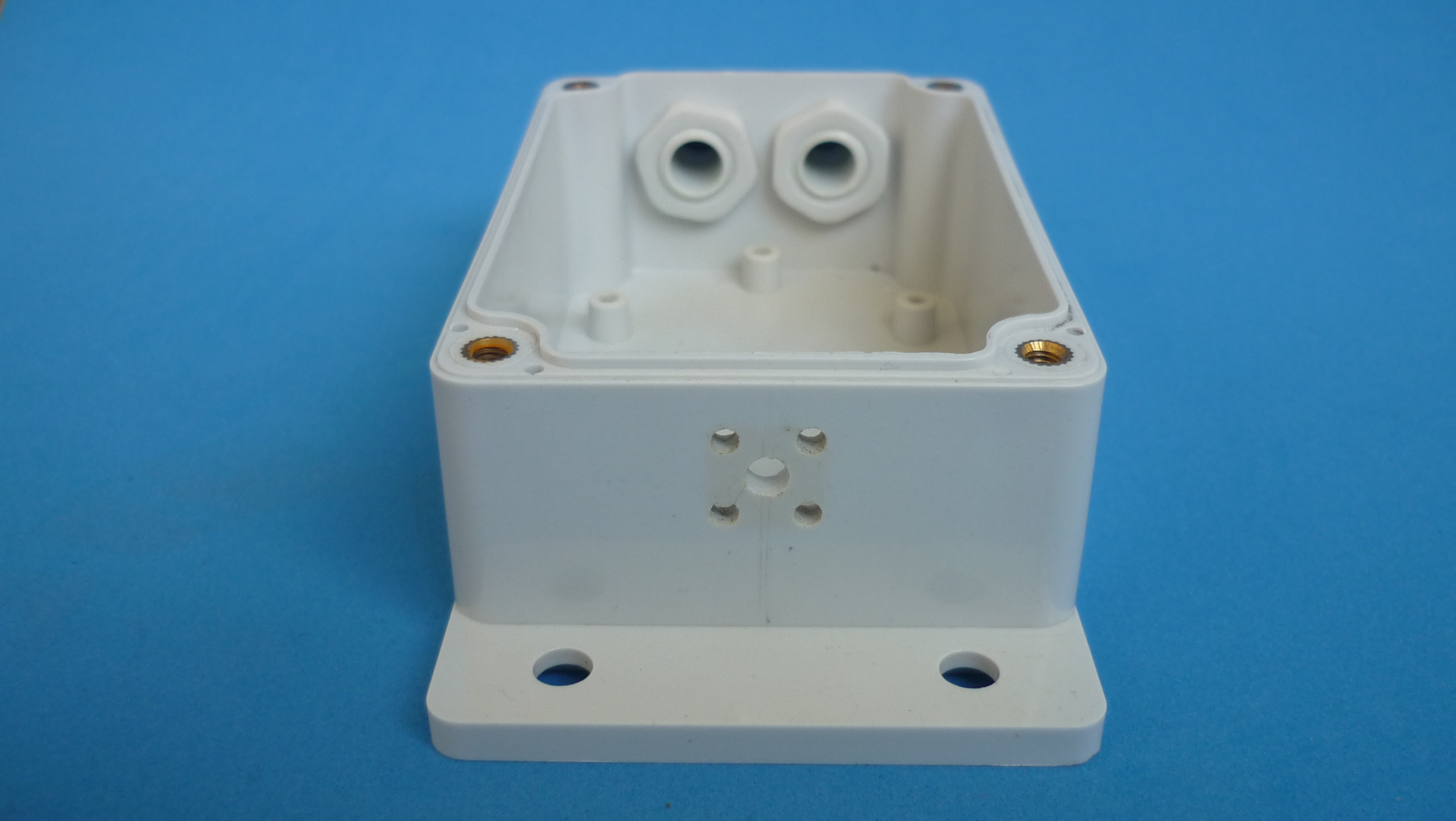
Fix antenna connector, circuit board and power cable.
-
Fix antenna connector to the enclosure with the screws and nylon nuts
-
Pass power cable through cable gland, let the adjusting nuts a little bit unscrewed
-
Place PCB inside enclosure and fix it using the self tapping screws
-
Connect power cable to screw terminals, antenna cable to LoRa module, and tight cable gland nut. Some experimentation with the order of the aforementioned steps will be required to find the easiest way to assembly.
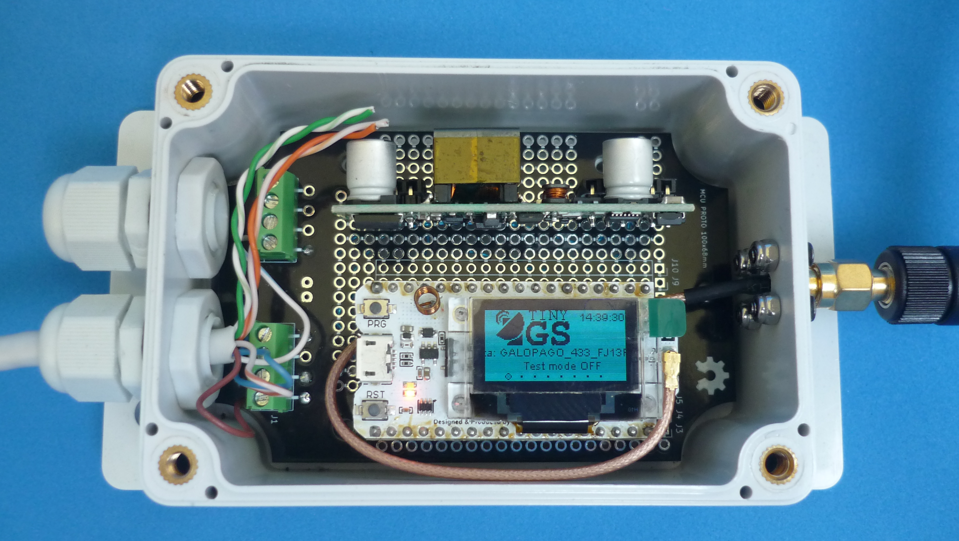
Firmware download.
Once the power connection was verified (usually the modules came with some sort of test firmware, so when the power is plugged some data will appear on the screen), connect the LoRa module to a computer using a USB cable, and follow the steps of the TinyGS wiki
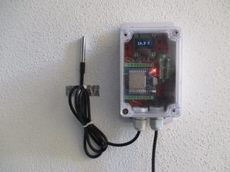
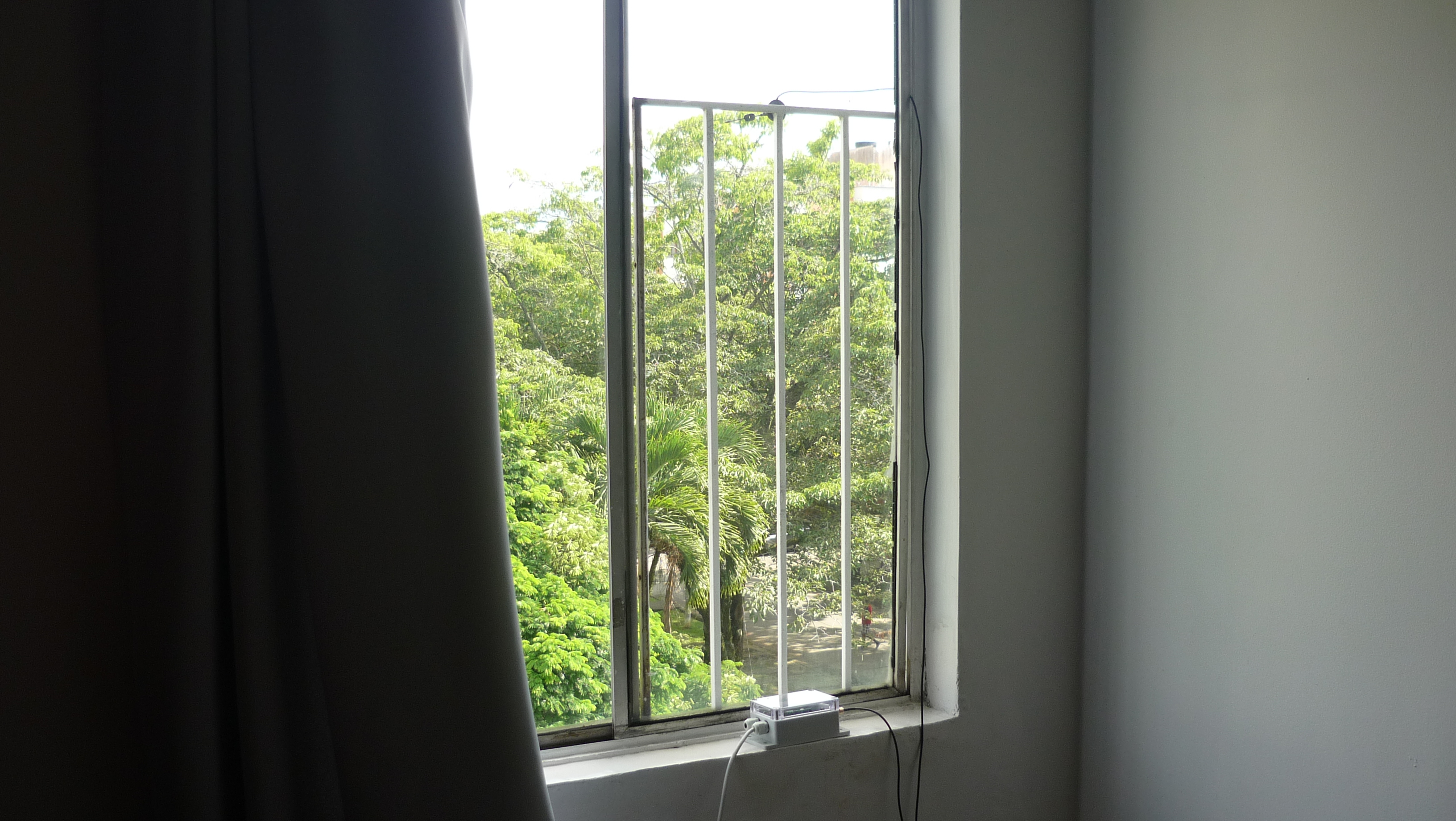
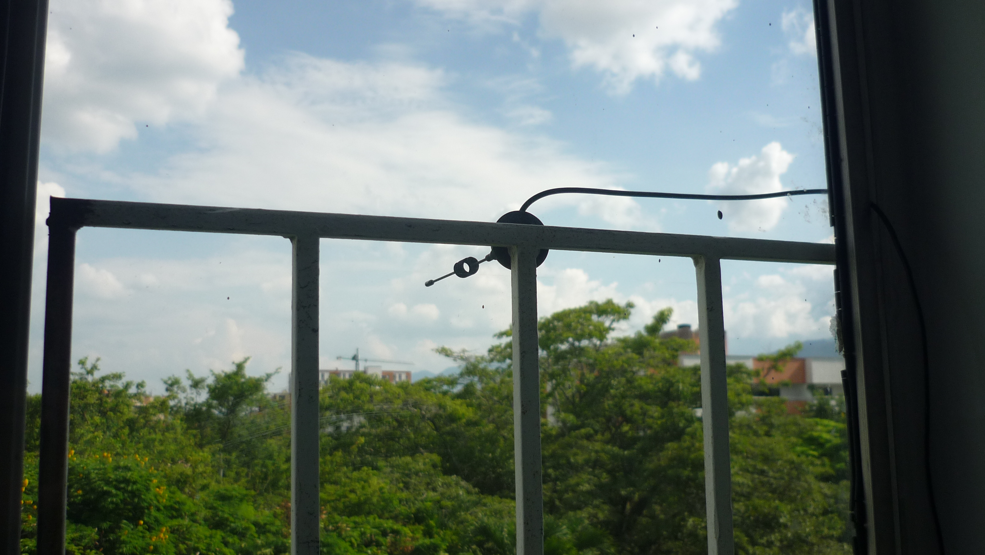
Antenna placement.
The antenna must be placed where there is the clearest view of the sky (on the roof or on a long pole) and away from walls or metal structures. In some houses it is not possible so, many tests on the windows must be carried out to obtain the best result
For outdoor installation, seal the second cable gland with a piece of rubber, wrap some self fusing tape around antenna metallic parts, and put a bit of neutral cure silicone sealant over the screws. Avoid using an acidic silicone sealant (those that smell like vinegar) as it oxidizes screws and metallic parts
Results
Due to the specific logistic conditions of this test, access to the roof was not possible and permanent structures could not be installed outside the windows, so the following configuration was tested: the receiver box would be placed inside, and a temporary magnetic mounted antenna on the outside.
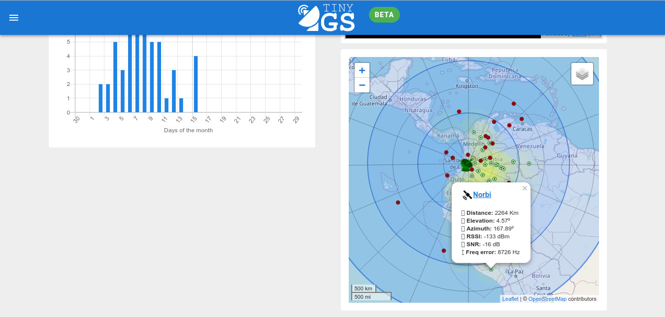
The antenna was purchased at a local store without any optimization or adjustment. The test was carried out in Cali, Colombia, the longest range transmission was received from NORBY satellite over Arequipa, Peru. The distance is about 2265 Km in line of sight, nothing bad for a home-assembled satellite receiver, with a budget of approximately 40 EUR and no adjustment required
Variants.
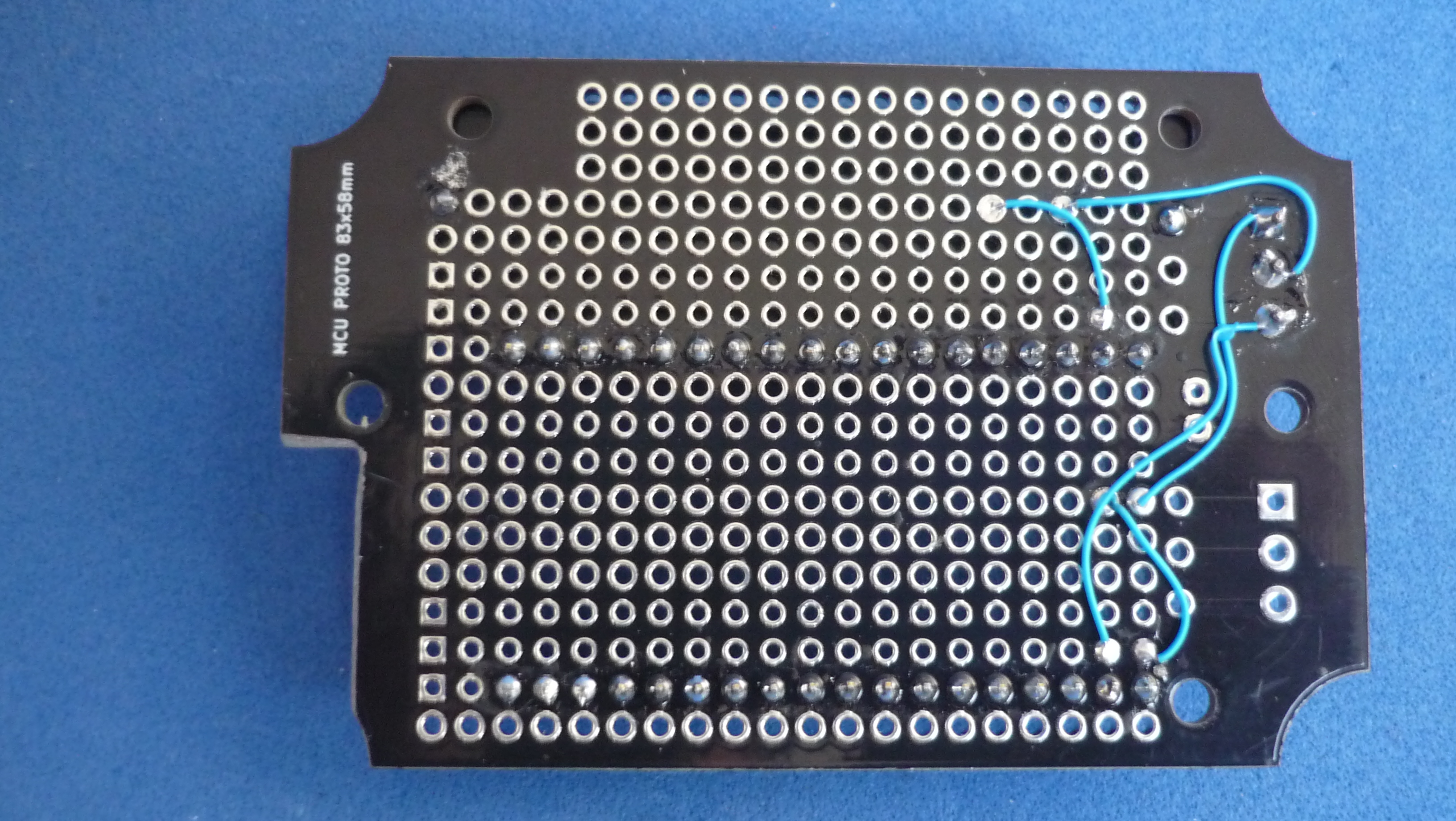
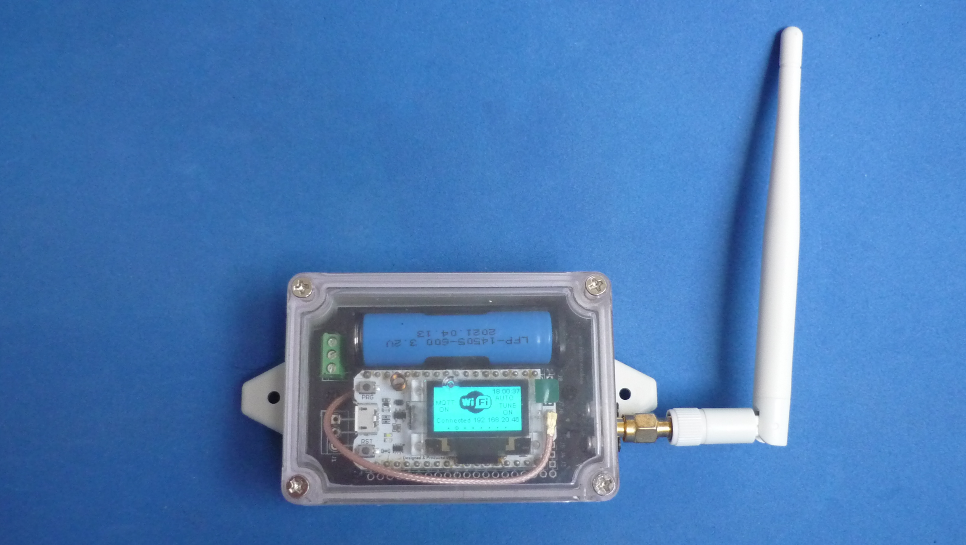
A portable version of the ground station has been developed, it uses a smaller enclosure and is powered by a battery. It was designed to be a temporary-mobile station which connects to a mobile phone via WiFi. It uses a 3.2v LiFePo4 battery, therefore no voltage regulator was required, the battery is connected directly to the 3.3v power pin of the LoRa module
The same hardware (fixed or mobile versions) could be used for another type of projects, such as aprs.fi, which is of particular interest to amateur radio operators. The hardware is 100% compatible and only requires a firmware change
| Optional components for mobile version | Buy link | Datasheet |
|---|---|---|
| Generic 83x58x33mm waterproof enclosure box | buy it | AK10019-A1.pdf |
| AA Battery holder for PCB | buy it | BH311.pdf |
| LiFePo4 3.2V 14500 AA Rechargeable battery | buy it | Lifepo4-3.2V-14500-Rechargeable-battery-AA.pdf |
| Printed Circuit Board | Buy link | Source files repository |
|---|---|---|
| Prototype circuit board for 83x58mm enclosure | buy it | mcu-proto-83x58mm |